This thread has been locked.

If you have a related question, please click the "Ask a related question" button in the top right corner. The newly created question will be automatically linked to this question.

eeprom 24c02 interface using I2C with F28069


Hi,

       I am trying interface eeprom 24c02 IC using I2C with F28069.I want to write multiple Write byte constructively and want to read random address read and Multiple read byte opearation.

  I am using sample code of I2C_eeprom of F28069 for write 2 byte on 0x0001 and 0x0002 memory add. location and also read same location. after read I get same data which is i write on 0x0002.

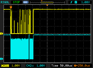
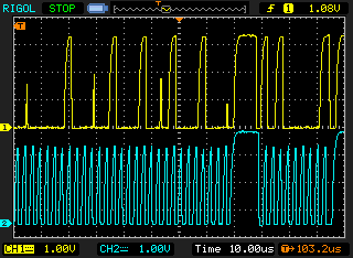
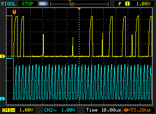
Please find attached waveform which I captured foe 2 byte write operation.

From which I knew only first data has been written.

Please help me for write multiple write data.

waiting for reply.

Regards,

Sagar 

  • Hello Sagar,

    Seems that still nobody can help you in your case (random read and write-read multiple bytes).

    However, I want you to confirm that your write byte and read byte function work properly or not (the ones that you said they worked).

    If you test them, for example:

    WriteByte(addr1, data1);

    addr1Content = ReadByte(addr1);

    WriteByte(addr2, data2);

    addr2Content = ReadByte(addr2);

    WriteByte(addr3, data3);

    addr3Content = ReadByte(addr3);

    WriteByte(addr50, data50);

    addr50Content = ReadByte(addr50);

    etc ... (sequentially in main loop, not one by one)

    will addr1Content, addr2Content, addr3Content, addr50Content be the data that you expected?

    Please confirm, thanks!

    Best regards,

    Maria

  • Hi Maria,

      Thanks for the reply.

    I am doing the same way  operation write and read.I got the expected data.But If do the following way,

     WriteByte(addr1, data1);

    WriteByte(addr2, data2);

    addr1Content = ReadByte(addr1);

    addr2Content = ReadByte(addr2);

    addr1Content and addr2Content are same value i.e. data2

    after that  I ma doing only 

     WriteByte(addr1, data1);

    WriteByte(addr2, data2);

    for testing purpose .I checked the wave forms on DSO. Please find attached files of wave forms.If you observed the waveform you will find that only first data was written.second is uncompleted.but  In s/w its look 2nd data was also written.

    Waiting for reply.

  • Hello Maria,

    Waiting for reply.

    Regards,

    sagar

  • sagar yadav1 said:

    WriteByte(addr1, data1);

    WriteByte(addr2, data2);

    If you put delay between writing process (for example 5ms), and then read them, what will be the result?

  • Hello Sagar,

    Maybe this is the problem (sorry that I can't test it, so please test it):

    Based on this website:

    http://www.totalphase.com/support/articles/200350096-How-to-Read-and-Write-to-an-I2C-EEPROM-Using-the-Aardvark-adapter-and-Control-Center

    The write operation used here to the AT24C02 is Byte Write. The Byte Write operation to the AT24C02 requires 7 bit device address, one byte memory address, and one or more bytes of memory data.

    So, no high byte adress, just put low byte address.

    Uint16 I2CA_WriteData(struct I2CMSG *msg)
    {
       Uint16 i;

       // Wait until the STP bit is cleared from any previous master communication.
       // Clearing of this bit by the module is delayed until after the SCD bit is
       // set. If this bit is not checked prior to initiating a new message, the
       // I2C could get confused.
       if (I2caRegs.I2CMDR.bit.STP == 1)
       {
          return I2C_STP_NOT_READY_ERROR;
       }

       // Setup slave address
       I2caRegs.I2CSAR = msg->SlaveAddress;

       // Check if bus busy
       if (I2caRegs.I2CSTR.bit.BB == 1)
       {
          return I2C_BUS_BUSY_ERROR;
       }

       // Setup number of bytes to send
       // MsgBuffer + Address
       I2caRegs.I2CCNT = msg->NumOfBytes+2; // And this is should be +1

       // Setup data to send
       I2caRegs.I2CDXR = msg->MemoryHighAddr;
       I2caRegs.I2CDXR = msg->MemoryLowAddr;
    // for (i=0; i<msg->NumOfBytes-2; i++)
       for (i=0; i<msg->NumOfBytes; i++)
       {
          I2caRegs.I2CDXR = *(msg->MsgBuffer+i);
       }

       // Send start as master transmitter
       I2caRegs.I2CMDR.all = 0x6E20;

       return I2C_SUCCESS;
    }

    Please try and let us know the result.

    Best regards,

    Maria

  • Hello Maria,

    Thanks for continue support.

    I will do the changes as per your suggestion & let you know the result.

    Bear Regards,

    Sagar

  • Hello Sagar,

    I don't think what I mentioned before is correct.

    Based on the datasheet, the address of EEPROM should be in word, however, what is the result on your test?

    I will share you my i2c code using 24LC256, it is very simple and doesn't use interrupt, so it is easier to follow the flow. The code is for F28027 but the flow for F28069 is the same. The interesting thing that you should try is to put delay. I put 5ms delay in write function as the maximum delay between STOP and next START condition is 5ms for 24LC256. I read that this is the same for at24c02 so you can try.

    //#############################################################################
    //
    //  File:   f2802x_examples_ccsv4/i2c_eeprom/Example_F2802xI2c_eeprom.c
    //
    //  Title:  F2802x I2C EEPROM Example
    //
    //  Group:          C2000
    //  Target Device:  TMS320F2802x
    //
    //! \addtogroup example_list
    //!  <h1>I2C EEPROM</h1>
    //!
    //!   This program will write 1-14 words to EEPROM and read them back.
    //!   The data written and the EEPROM address written to are contained
    //!   in the message structure, I2cMsgOut1. The data read back will be
    //!   contained in the message structure I2cMsgIn1.
    //!
    //!   This program will work with the on-board I2C EEPROM supplied on
    //!   the F2802x eZdsp or another EEPROM connected to the devices I2C bus
    //!   with a slave address of 0x50
    //
    //  (C) Copyright 2012, Texas Instruments, Inc.
    //#############################################################################
    // $TI Release: f2802x Support Library v210 $
    // $Release Date: Mon Sep 17 09:13:31 CDT 2012 $
    //#############################################################################
    
    #include "DSP28x_Project.h"     // Device Headerfile and Examples Include File
    
    // Note: I2C Macros used in this example can be found in the
    // DSP2802x_I2C_defines.h file
    
    // Prototype statements for functions found within this file.
    void I2CA_Init(void);
    Uint16 ReadEeprom(Uint16 e2promaddress);
    void WriteEeprom(Uint16 e2promaddress, Uint16 data);
    
    
    Uint32 DataRead[256];//] = { 0,0,0,0,0,0,0,0,0,0};
    
    void main(void)
    {
    
    // Step 1. Initialize System Control:
    // PLL, WatchDog, enable Peripheral Clocks
    // This example function is found in the DSP2802x_SysCtrl.c file.
       InitSysCtrl();
    
    // Step 2. Initalize GPIO:
    // This example function is found in the DSP2802x_Gpio.c file and
    // illustrates how to set the GPIO to it's default state.
    // InitGpio();
    // Setup only the GP I/O only for I2C functionality
       InitI2CGpio(); // using GPIO 32 and 33
    
    // Step 3. Clear all interrupts and initialize PIE vector table:
    // Disable CPU interrupts
       DINT;
    
    // Initialize PIE control registers to their default state.
    // The default state is all PIE interrupts disabled and flags
    // are cleared.
    // This function is found in the DSP2802x_PieCtrl.c file.
       InitPieCtrl();
    
    // Disable CPU interrupts and clear all CPU interrupt flags:
       IER = 0x0000;
       IFR = 0x0000;
    
       // If running from flash copy RAM only functions to RAM
    #ifdef _FLASH
       memcpy(&RamfuncsRunStart, &RamfuncsLoadStart, (size_t)&RamfuncsLoadSize);
    #endif
    
    // Initialize the PIE vector table with pointers to the shell Interrupt
    // Service Routines (ISR).
    // This will populate the entire table, even if the interrupt
    // is not used in this example.  This is useful for debug purposes.
    // The shell ISR routines are found in DSP2802x_DefaultIsr.c.
    // This function is found in DSP2802x_PieVect.c.
       InitPieVectTable();
    
    
       // Step 4. Initialize all the Device Peripherals:
       // This function is found in DSP2802x_InitPeripherals.c
       // InitPeripherals(); // Not required for this example
          I2CA_Init();
          DELAY_US(100);
       // Step 5. User specific code
    
          EINT;
    
       unsigned int j;
       j =0;
    
       // Application loop
       for(;;)
       {
    	   //WriteEeprom(j, 10+j);
    	   //WriteEeprom(j+1, 10+j+1);
    
    	   DataRead[j] = ReadEeprom(j);
    	   //DataRead[j+1] = (ReadEeprom(j+1) << 8) | DataRead[j] ;
    	   DataRead[j+1] = ReadEeprom(j+1) ;
    
    	   j=j+2;
    
    	   if (j>=200)
    		   j = 0;
    
       }   // end of for(;;)
    }   // end of main
    
    void I2CA_Init(void)
    {
    		I2caRegs.I2CMDR.all 	= 0x0000;
    	   // Initialize I2C
    	   I2caRegs.I2CSAR = 0x0050;        // Slave address - EEPROM control code
    
    	   // I2CCLK = SYSCLK/(I2CPSC+1)
    	   #if (CPU_FRQ_40MHZ||CPU_FRQ_50MHZ)
    	     I2caRegs.I2CPSC.all = 4;       // Prescaler - need 7-12 Mhz on module clk
    	   #endif
    
    	   #if (CPU_FRQ_60MHZ)
    	     I2caRegs.I2CPSC.all = 5;  //6     // Prescaler - need 7-12 Mhz on module clk
    	   #endif
    	   I2caRegs.I2CCLKL = 10;        	// NOTE: must be non zero
    	   I2caRegs.I2CCLKH = 5;         	// NOTE: must be non zero
    //	   I2caRegs.I2CIER.all = 0x24;      // Enable SCD & ARDY interrupts
    
    	   I2caRegs.I2CMDR.all = 0x0020;    // Take I2C out of reset
    	                                    // Stop I2C when suspended
    
    	   I2caRegs.I2CFFTX.all = 0x6000;   // Enable FIFO mode and TXFIFO
    	   I2caRegs.I2CFFRX.all = 0x2040;   // Enable RXFIFO, clear RXFFINT,
    
    
       return;
    }
    
    
    Uint16 ReadEeprom(Uint16 e2promaddress)
    {
    	Uint16 addresslow;
    	Uint16 addresshigh;
    	Uint16 tempdata;
    
    	I2caRegs.I2CMDR.bit.IRS = 1; 				// reset I2C
    	while (I2caRegs.I2CSTR.bit.BB == 1);		// busy loop
    	I2caRegs.I2CSTR.bit.SCD = 1;				// Clear the SCD bit (stop condition bit)
    	while(I2caRegs.I2CMDR.bit.STP == 1);		// stop bit loop
    
    	addresshigh			= e2promaddress>>8;
    	addresslow			= e2promaddress;
    	I2caRegs.I2CSAR 	= 0x0050;
    
    	while (I2caRegs.I2CSTR.bit.BB == 1);
    	I2caRegs.I2CMDR.all = 0x2620;				// start, no stop bit, master, tx, reset I2C
    	I2caRegs.I2CCNT		= 0x0002;
    	I2caRegs.I2CDXR		= addresshigh;
    	I2caRegs.I2CDXR		= addresslow;
    	while(!I2caRegs.I2CSTR.bit.ARDY);			// all ready?
    
    	I2caRegs.I2CMDR.all = 0x2C20;				// start, stop bit when CNT =0, master, rx, reset I2C
    	I2caRegs.I2CCNT		= 1;
    
    	if(I2caRegs.I2CSTR.bit.NACK == 1)
    	{
    		 I2caRegs.I2CSTR.all = I2C_CLR_NACK_BIT; 	// 0x0002
    	}
    	I2caRegs.I2CMDR.bit.STP = 1;					// stop bit when CNT=0
    
    	while(!I2caRegs.I2CSTR.bit.SCD);				// stop bit detected?
    
    	//tempdata	= I2caRegs.I2CDRR << 8; 			// read data
    	tempdata	= I2caRegs.I2CDRR;
    
    	DELAY_US(100);
    
    	return(tempdata);
    }
    
    
    void WriteEeprom(Uint16 e2promaddress, Uint16 data)
    {
    	Uint16 addresslow;
    	Uint16 addresshigh;
    
    	I2caRegs.I2CMDR.bit.IRS = 1; 			// reset I2C
    
    	addresshigh			= (e2promaddress>>8)&0x00FF;
    	addresslow			= e2promaddress&0x00FF;
    	I2caRegs.I2CSAR 	= 0x0050;			// EEPROM control bits + address (A0-A2). for 24LC256, 0 1 0 1 0 A0 A1 A2
    
    	while (I2caRegs.I2CSTR.bit.BB == 1);
    
    	I2caRegs.I2CCNT		= 3	;
    	I2caRegs.I2CMDR.all = 0x6E20; 				//start, stop, no rm, reset i2c
    	I2caRegs.I2CDXR		= addresshigh;
    	I2caRegs.I2CDXR		= addresslow;
    //	I2caRegs.I2CDXR		= (data >> 8) & 0x00FF;	// high byte data
    	I2caRegs.I2CDXR		= data;					// low byte data
    	I2caRegs.I2CMDR.bit.STP = 1;  				// stop bit when CNT=0
    
    	while(!I2caRegs.I2CSTR.bit.SCD);			// stop bit detected?
    
    	DELAY_US(5000);								// 5ms = write cycle time of 24LC256 - based on datasheet 24LC256
    
    	return;
    }
    
    //===========================================================================
    // No more.
    //===========================================================================
    

    Good luck!

    Best regards,

    Maria