This thread has been locked.

If you have a related question, please click the "Ask a related question" button in the top right corner. The newly created question will be automatically linked to this question.

Three phase spwm, phase shift problem

Hello to everyone,

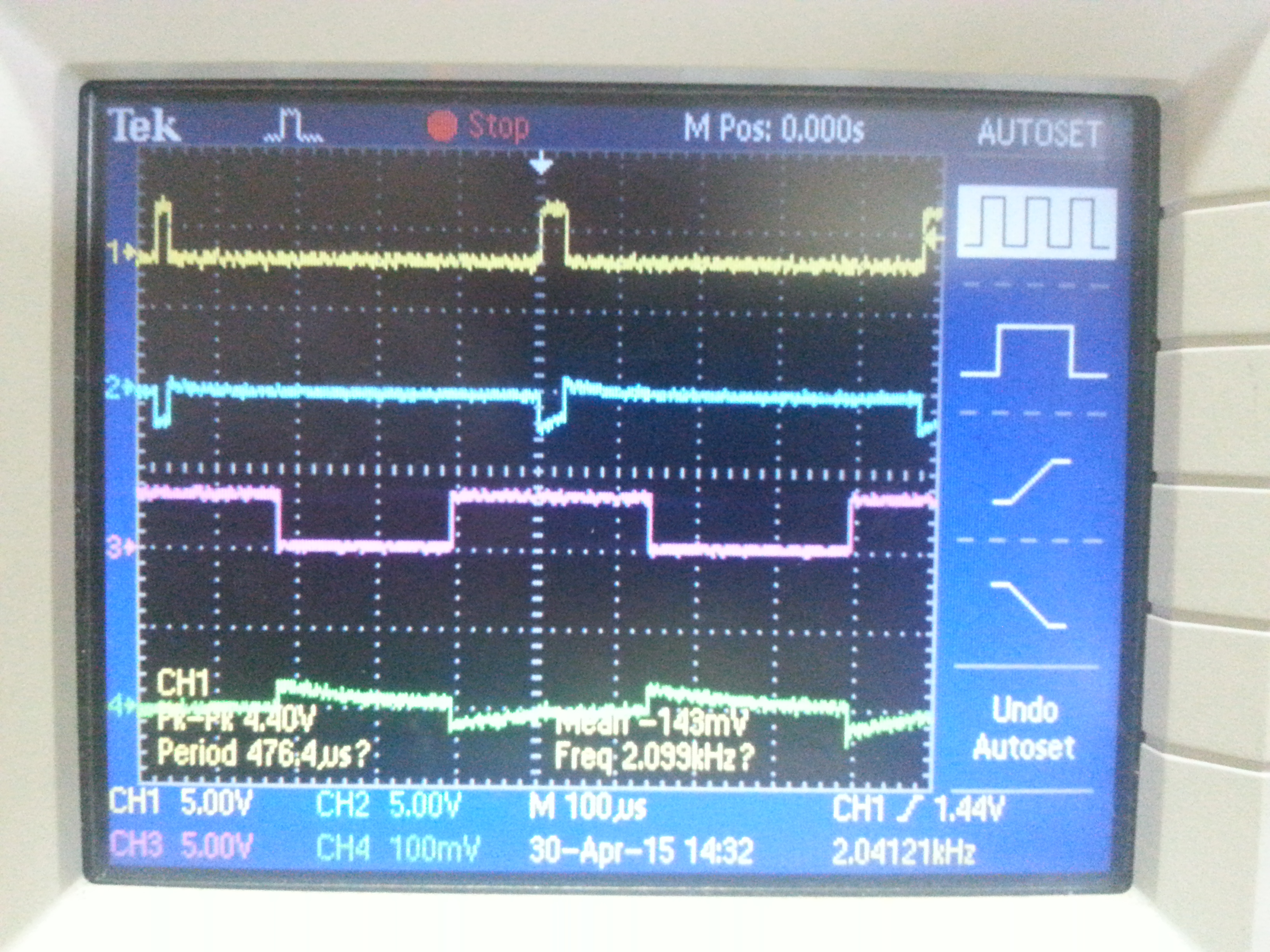
I am trying to program my C2000 launchpad in order to have an spwm with 2kHz switching frequency and 50Hz sine wave. The spwm must be for a 3 phase inverter with 120deg difference between each phase. My program read the sine table, which is stored in the ROM, and sets the CMPA register for the three EPWM when the timer0 gives an interrupt (every 20ms/512). Then I set the phase shift to be 120deg for each EPWM module. But the phase voltage as well as the line voltage from my inverter is not correct. The idea of having a delay on each EPWM is the same, as having three different sine waves with 120deg difference in order to set each CMPA registers?

Here is my code: please free to comment for any mistakes or advices. Thanks in advance.

//-----------------------------------------------------------------------------------
//-----------------------------------------------------------------------------------
// 	
//
//
//	The user sets the frequency of the SPWM by setting appropriately the
//  EPWM1_TIMER_TBPRD variable. The frequency of the PWM,up and down mode,
//  obeys the equations: TPWM=2xTBPRDxTTBCLK, TTBCLK=SYSCLKOUT/(HSPCLKDIVxCLKDIV).
//  By default: HSPCLKDIV=2, CLKDIV=1.
//
//	The sine for the PWM is read by the chip ROM. The sine table consists of
//  512 elements.
//  The frequency of sinusoidal PWM is defined by the period of the timer0 interrupt.
//  For 50Hz the sine table must be read, entirely in 20msec. This means that the
//  timer0 interrupt must occur in every 20/512 msec.
//  The general type for the Ttimer=Tsin*Fcpu/index.
//
//------------------------------------------------------------------------------------
//------------------------------------------------------------------------------------


#include <stdio.h>
#include <file.h>

#include "DSP28x_Project.h"   // DSP28x Headerfile
#include "f2802x_common/include/F2802x_GlobalPrototypes.h"

#include "f2802x_common/include/pll.h"
#include "f2802x_common/include/clk.h"
#include "f2802x_common/include/wdog.h"

#include "f2802x_common/include/flash.h"
#include "f2802x_common/include/gpio.h"
#include "f2802x_common/include/pie.h"
#include "f2802x_common/include/adc.h"
#include "f2802x_common/include/sci.h"
#include "f2802x_common/include/sci_io.h"
#include "f2802x_common/include/pwm.h"
#include "f2802x_common/include/timer.h"
#include "f2802x_common/include/IQmathLib.h" //IQmath Library header file


extern void DSP28x_usDelay(Uint32 Count);
#pragma DATA_SECTION(sine_table,"IQmathTables"); //IQmath ROM sine table
_iq30 sine_table[512];


//Interrupt prototype function for timer0
interrupt void cpu_timer0_isr(void);
void update_compare(void);

//Global PWM variables
#define EPWM1_TIMER_TBPRD  14634 // Period register for 2050.2Hz
#define PHASE 120.0				// Defines the real in degrees phase between phases, 120deg
#define TTIMERREG 2343          // Timer interrupt for 50Hz SPWM
Uint16 EPWM_PHASE=(EPWM1_TIMER_TBPRD*PHASE/180.0); //The phase as seen from the EPWM module
Uint16 duty_cycle_A=1000;	// Set duty 50% initially
Uint16 duty_cycle_B=1000;	// Set duty 50% initially
Uint16 index=0;
Uint16 DEADTIME_R=5.0;
Uint16 DEADTIME_F=5.0;
Uint16 y=0.0;


// Handles setup
CPU_Handle myCpu;
PLL_Handle myPll;
WDOG_Handle myWDog;
CLK_Handle myClk;
ADC_Handle myAdc;
FLASH_Handle myFlash;
GPIO_Handle myGpio;
PIE_Handle myPie;
SCI_Handle mySci;
PWM_Handle PWMA,PWMB,PWMC;
TIMER_Handle myTimer0;


// Handles initialization
void setup_handles()
{

    myClk = CLK_init((void *)CLK_BASE_ADDR, sizeof(CLK_Obj));
    myPll = PLL_init((void *)PLL_BASE_ADDR, sizeof(PLL_Obj));
    myWDog = WDOG_init((void *)WDOG_BASE_ADDR, sizeof(WDOG_Obj));
    myCpu = CPU_init((void *)NULL, sizeof(CPU_Obj));

    myFlash = FLASH_init((void *)FLASH_BASE_ADDR, sizeof(FLASH_Obj));
    myGpio = GPIO_init((void *)GPIO_BASE_ADDR, sizeof(GPIO_Obj));
    myPie = PIE_init((void *)PIE_BASE_ADDR, sizeof(PIE_Obj));
    mySci = SCI_init((void *)SCIA_BASE_ADDR, sizeof(SCI_Obj));
    myAdc = ADC_init((void *)ADC_BASE_ADDR, sizeof(ADC_Obj));
    PWMA = PWM_init((void *)PWM_ePWM1_BASE_ADDR, sizeof(PWM_Obj));
    PWMB = PWM_init((void *)PWM_ePWM2_BASE_ADDR, sizeof(PWM_Obj));
    PWMC = PWM_init((void *)PWM_ePWM3_BASE_ADDR, sizeof(PWM_Obj));
    myTimer0 = TIMER_init((void *)TIMER0_BASE_ADDR, sizeof(TIMER_Obj));

}

//System Initialization
void init_system()
{
  //Disable watchcdog
  WDOG_disable(myWDog);
  //Device calibration for the adc
  (*Device_cal)();
  //Sets the internal oscillator source
  CLK_setOscSrc(myClk, CLK_OscSrc_Internal);

  // Setup the PLL for x10 /2 which will yield 60Mhz = 10Mhz * 12 / 2
  PLL_setup(myPll, PLL_Multiplier_12, PLL_DivideSelect_ClkIn_by_2);

  //Disable the PIE peripheral and all the interupts
  PIE_disable(myPie);
  PIE_disableAllInts(myPie);
  CPU_disableGlobalInts(myCpu);
  CPU_clearIntFlags(myCpu);

#ifdef _FLASH
    memcpy(&RamfuncsRunStart, &RamfuncsLoadStart, (size_t)&RamfuncsLoadSize);
#endif
}

//GPIO initialization
void gpio_init()
{
	// Initialize GPIO for the EPWM1A and EPWM1B
	GPIO_setPullUp(myGpio, GPIO_Number_0, GPIO_PullUp_Disable);
	GPIO_setPullUp(myGpio, GPIO_Number_1, GPIO_PullUp_Disable);
	GPIO_setMode(myGpio, GPIO_Number_0, GPIO_0_Mode_EPWM1A);
	GPIO_setMode(myGpio, GPIO_Number_1, GPIO_1_Mode_EPWM1B);
	GPIO_setDirection(myGpio,GPIO_Number_0,GPIO_Direction_Output);
	GPIO_setDirection(myGpio,GPIO_Number_1,GPIO_Direction_Output);

	// Initialize GPIO for the EPWM2A and EPWM2B
	GPIO_setPullUp(myGpio, GPIO_Number_2, GPIO_PullUp_Disable);
	GPIO_setPullUp(myGpio, GPIO_Number_3, GPIO_PullUp_Disable);
	GPIO_setMode(myGpio, GPIO_Number_2, GPIO_2_Mode_EPWM2A);
	GPIO_setMode(myGpio, GPIO_Number_3, GPIO_3_Mode_EPWM2B);
	GPIO_setDirection(myGpio,GPIO_Number_2,GPIO_Direction_Output);
	GPIO_setDirection(myGpio,GPIO_Number_3,GPIO_Direction_Output);

	// Initialize GPIO for the EPWM2A and EPWM2B
	GPIO_setPullUp(myGpio, GPIO_Number_4, GPIO_PullUp_Disable);
	GPIO_setPullUp(myGpio, GPIO_Number_5, GPIO_PullUp_Disable);
	GPIO_setMode(myGpio, GPIO_Number_4, GPIO_4_Mode_EPWM3A);
	GPIO_setMode(myGpio, GPIO_Number_5, GPIO_5_Mode_EPWM3B);
	GPIO_setDirection(myGpio,GPIO_Number_4,GPIO_Direction_Output);
	GPIO_setDirection(myGpio,GPIO_Number_5,GPIO_Direction_Output);
}

//PWM settings
void pwma_init()
{

	// PWMA initialization
	CLK_enablePwmClock(myClk, PWM_Number_1);

	//PWMA initialiazation

	// Setup TBCLK
	PWM_setCounterMode(PWMA,PWM_CounterMode_UpDown);  // Count up-down
	PWM_setPeriod(PWMA,EPWM1_TIMER_TBPRD);            // Set timer period
	PWM_disableCounterLoad(PWMA);                     // Disable phase loading
	PWM_setSyncMode(PWMA,PWM_SyncMode_CounterEqualZero);
	PWM_setPhase(PWMA,0x0000);                        // Phase is 0
	PWM_setCount(PWMA, 0x0000);                       // Clear counter
	PWM_setClkDiv(PWMA, PWM_ClkDiv_by_1);
	PWM_setHighSpeedClkDiv(PWMA, PWM_HspClkDiv_by_1);     // Clock ratio to SYSCLKOUT

	 // Setup shadowing
	PWM_setShadowMode_CmpA(PWMA, PWM_ShadowMode_Shadow);
	PWM_setShadowMode_CmpB(PWMA, PWM_ShadowMode_Shadow);
	PWM_setLoadMode_CmpA(PWMA, PWM_LoadMode_Zero);
	PWM_setLoadMode_CmpB(PWMA, PWM_LoadMode_Zero);

	PWM_setCmpA(PWMA,1000); //Initial duty cycle
	PWM_setCmpB(PWMA,1000);

	// Set actions
	PWM_setActionQual_CntUp_CmpA_PwmA(PWMA, PWM_ActionQual_Set);      // Set PWM1A on event A, up count
	PWM_setActionQual_CntDown_CmpA_PwmA(PWMA, PWM_ActionQual_Clear);  // Clear PWM1A on event A, down count
	PWM_setActionQual_CntUp_CmpB_PwmB(PWMA, PWM_ActionQual_Clear);      // Set PWM1B on event B, up count
	PWM_setActionQual_CntDown_CmpB_PwmB(PWMA, PWM_ActionQual_Set);  // Clear PWM1B on event B, down count

	//Set DeadBand Control
	PWM_setDeadBandOutputMode(PWMA, PWM_DeadBandOutputMode_EPWMxA_Rising_EPWMxB_Falling);
	PWM_setDeadBandPolarity(PWMA, PWM_DeadBandPolarity_EPWMxB_Inverted);
	PWM_setDeadBandInputMode(PWMA, PWM_DeadBandInputMode_EPWMxA_Rising_and_Falling);
	PWM_setDeadBandRisingEdgeDelay(PWMA, DEADTIME_R);
	PWM_setDeadBandFallingEdgeDelay(PWMA, DEADTIME_F);
//--------------------------------------------------------------------------------------------------------------------
//--------------------------------------------------------------------------------------------------------------------

	//PWMB initialization

	CLK_enablePwmClock(myClk, PWM_Number_2);

	 // Setup TBCLK
	PWM_setCounterMode(PWMB,PWM_CounterMode_UpDown);  // Count up-down
	PWM_setPeriod(PWMB,EPWM1_TIMER_TBPRD);  // Set timer period
	PWM_enableCounterLoad(PWMB);
	PWM_setPhaseDir(PWMB,PWM_PhaseDir_CountDown);
	PWM_setSyncMode(PWMB,PWM_SyncMode_EPWMxSYNC);
	PWM_setPhase(PWMB,EPWM_PHASE);    // Phase is 120 degrees
	PWM_setCount(PWMB, 0x0000);                       // Clear counter
	PWM_setClkDiv(PWMB, PWM_ClkDiv_by_1);
	PWM_setHighSpeedClkDiv(PWMB, PWM_HspClkDiv_by_1);     // Clock ratio to SYSCLKOUT

	 // Setup shadowing
	PWM_setShadowMode_CmpA(PWMB, PWM_ShadowMode_Shadow);
	PWM_setShadowMode_CmpB(PWMB, PWM_ShadowMode_Shadow);
	PWM_setLoadMode_CmpA(PWMB, PWM_LoadMode_Zero);
	PWM_setLoadMode_CmpB(PWMB, PWM_LoadMode_Zero);

	PWM_setCmpA(PWMB,1000); //Initial duty cycle
	PWM_setCmpB(PWMB,1000);

	// Set actions
	PWM_setActionQual_CntUp_CmpA_PwmA(PWMB, PWM_ActionQual_Set);      // Set PWM2A on event A, up count
	PWM_setActionQual_CntDown_CmpA_PwmA(PWMB, PWM_ActionQual_Clear);  // Clear PWM2A on event A, down count
	PWM_setActionQual_CntUp_CmpB_PwmB(PWMB, PWM_ActionQual_Clear);      // Set PWM2B on event B, up count
	PWM_setActionQual_CntDown_CmpB_PwmB(PWMB, PWM_ActionQual_Set);  // Clear PWM2B on event B, down count

	//Set DeadBand Control
	PWM_setDeadBandOutputMode(PWMB, PWM_DeadBandOutputMode_EPWMxA_Rising_EPWMxB_Falling);
	PWM_setDeadBandPolarity(PWMB, PWM_DeadBandPolarity_EPWMxB_Inverted);
	PWM_setDeadBandInputMode(PWMB, PWM_DeadBandInputMode_EPWMxA_Rising_and_Falling);
    PWM_setDeadBandRisingEdgeDelay(PWMB, DEADTIME_R);
    PWM_setDeadBandFallingEdgeDelay(PWMB, DEADTIME_F);
//---------------------------------------------------------------------------------------------------------------
//---------------------------------------------------------------------------------------------------------------

	//PWMC initialization

	CLK_enablePwmClock(myClk, PWM_Number_3);

	 // Setup TBCLK
	PWM_setCounterMode(PWMC,PWM_CounterMode_UpDown);  // Count up-down
	PWM_setPeriod(PWMC,EPWM1_TIMER_TBPRD); // Set timer period
	PWM_enableCounterLoad(PWMC);
	PWM_setPhaseDir(PWMC,PWM_PhaseDir_CountUp);
	PWM_setSyncMode(PWMC,PWM_SyncMode_EPWMxSYNC);
	PWM_setPhase(PWMC,EPWM_PHASE);                    // Phase is 120
	PWM_setCount(PWMC, 0x0000);                       // Clear counter
	PWM_setClkDiv(PWMC, PWM_ClkDiv_by_1);
	PWM_setHighSpeedClkDiv(PWMC, PWM_HspClkDiv_by_1);     // Clock ratio to SYSCLKOUT

	 // Setup shadowing
	PWM_setShadowMode_CmpA(PWMC, PWM_ShadowMode_Shadow);
	PWM_setShadowMode_CmpB(PWMC, PWM_ShadowMode_Shadow);
	PWM_setLoadMode_CmpA(PWMC, PWM_LoadMode_Zero);
	PWM_setLoadMode_CmpB(PWMC, PWM_LoadMode_Zero);

	PWM_setCmpA(PWMC,1000); //Initial duty cycle
	PWM_setCmpB(PWMC,1000);

	// Set actions
	PWM_setActionQual_CntUp_CmpA_PwmA(PWMC, PWM_ActionQual_Set);      // Set PWM3A on event A, up count
	PWM_setActionQual_CntDown_CmpA_PwmA(PWMC, PWM_ActionQual_Clear);  // Clear PWM3A on event A, down count
	PWM_setActionQual_CntUp_CmpB_PwmB(PWMC, PWM_ActionQual_Clear);      // Set PWM3B on event B, up count
	PWM_setActionQual_CntDown_CmpB_PwmB(PWMC, PWM_ActionQual_Set);  // Clear PWM3B on event B, down count

	//Set DeadBand Control
	PWM_setDeadBandOutputMode(PWMC, PWM_DeadBandOutputMode_EPWMxA_Rising_EPWMxB_Falling);
	PWM_setDeadBandPolarity(PWMC, PWM_DeadBandPolarity_EPWMxB_Inverted);
	PWM_setDeadBandInputMode(PWMC, PWM_DeadBandInputMode_EPWMxA_Rising_and_Falling);
	PWM_setDeadBandRisingEdgeDelay(PWMC, DEADTIME_R);
	PWM_setDeadBandFallingEdgeDelay(PWMC, DEADTIME_F);

	CLK_enableTbClockSync(myClk);
}

//PIE settings
void pie_init()
{
	PIE_enable(myPie);
	EALLOW;
	EDIS;
	PIE_registerPieIntHandler(myPie, PIE_GroupNumber_1, PIE_SubGroupNumber_7, (intVec_t)&cpu_timer0_isr);
	EDIS;
}

//Timer settings
void timer0_init()
{
	TIMER_stop(myTimer0);
	TIMER_setPeriod(myTimer0,TTIMERREG);
    TIMER_setPreScaler(myTimer0,0);
    TIMER_reload(myTimer0);
    TIMER_setEmulationMode(myTimer0, TIMER_EmulationMode_StopAfterNextDecrement);
    TIMER_enableInt(myTimer0);
    TIMER_start(myTimer0);
}

void main()
{

  setup_handles();
  init_system();
  gpio_init();
  pwma_init();
  pie_init();
  timer0_init();

  //Enables the CPU interrupt
  CPU_enableInt(myCpu, CPU_IntNumber_1);
  //Enables the interrupt  of the Timer0 for the PIE module
  PIE_enableTimer0Int(myPie);
  CPU_enableGlobalInts(myCpu);
  CPU_enableDebugInt(myCpu);


  //Forever Loop to see the results
  for(;;)

  	{

  	}
}

interrupt void cpu_timer0_isr(void)
{
   update_compare();

   // Acknowledge this interrupt to receive more interrupts from group 1
   PIE_clearInt(myPie, PIE_GroupNumber_1);
}

void update_compare(void)
{
	PWM_setCmpA(PWMA,_IQsat(_IQ30mpy((sine_table[index]+_IQ30(0.9999))/2,EPWM1_TIMER_TBPRD),EPWM1_TIMER_TBPRD,0));
	PWM_setCmpB(PWMA,_IQsat(_IQ30mpy((sine_table[index]+_IQ30(0.9999))/2,EPWM1_TIMER_TBPRD),EPWM1_TIMER_TBPRD,0));
	PWM_setCmpA(PWMB,_IQsat(_IQ30mpy((sine_table[index]+_IQ30(0.9999))/2,EPWM1_TIMER_TBPRD),EPWM1_TIMER_TBPRD,0));
	PWM_setCmpB(PWMB,_IQsat(_IQ30mpy((sine_table[index]+_IQ30(0.9999))/2,EPWM1_TIMER_TBPRD),EPWM1_TIMER_TBPRD,0));
	PWM_setCmpA(PWMC,_IQsat(_IQ30mpy((sine_table[index]+_IQ30(0.9999))/2,EPWM1_TIMER_TBPRD),EPWM1_TIMER_TBPRD,0));
	PWM_setCmpB(PWMC,_IQsat(_IQ30mpy((sine_table[index]+_IQ30(0.9999))/2,EPWM1_TIMER_TBPRD),EPWM1_TIMER_TBPRD,0));

	if (index++ >511) index = 0;
}


//---------------------------------------------

  • Hi Ioannis,what is the phase shift you are observing?
    Are the PWM o/ps looking as exoected? can you share some waveform capute?
  • I have just found the solution.

    For 120 degrees difference in the line voltage of the inverter, you have to compare three different sines (50 or 60Hz frequency) with 120 degrees  phase difference from each other. It is false to make a difference of 120 degrees between the epwm modules, bacause this difference is responding to the switching frequency of the epwm (2050 Hz in my example) and not the 50Hz output.

    So the solution is to read the sine three times with 120 phase difference and the epwm phase must be set to zero.

    Feel free to comment my code.

    //-----------------------------------------------------------------------------------
    //-----------------------------------------------------------------------------------
    // 	Ioannis Pallis, 2014
    //	This code implements 3-phase sinusoidal PWM.
    //
    //	The user sets the frequency of the SPWM by setting appropriately the
    //  EPWM1_TIMER_TBPRD variable. The frequency of the PWM,up and down mode,
    //  obeys the equations: TPWM=2xTBPRDxTTBCLK, TTBCLK=SYSCLKOUT/(HSPCLKDIVxCLKDIV).
    //  By default: HSPCLKDIV=2, CLKDIV=1.
    //
    //	The sine for the PWM is read by the chip ROM. The sine table consists of
    //  512 elements.
    //  The frequency of sinusoidal PWM is defined by the period of the timer0 interrupt.
    //  For 50Hz the sine table must be read, entirely in 20msec. This means that the
    //  timer0 interrupt must occur in every 20/512 msec.
    //  The general type for the is Ttimer=Tsin*Fcpu/index.
    //
    //  The 120 degrees difference of the sine are set by the variables:
    //  index = 0, zero degrees
    //  index2= 170, 120 degrees
    //  index3=340, for 240 degrees
    //
    //
    //------------------------------------------------------------------------------------
    //------------------------------------------------------------------------------------
    
    
    #include <stdio.h>
    #include <file.h>
    
    #include "DSP28x_Project.h"   // DSP28x Headerfile
    #include "f2802x_common/include/F2802x_GlobalPrototypes.h"
    
    #include "f2802x_common/include/pll.h"
    #include "f2802x_common/include/clk.h"
    #include "f2802x_common/include/wdog.h"
    
    #include "f2802x_common/include/flash.h"
    #include "f2802x_common/include/gpio.h"
    #include "f2802x_common/include/pie.h"
    #include "f2802x_common/include/adc.h"
    #include "f2802x_common/include/sci.h"
    #include "f2802x_common/include/sci_io.h"
    #include "f2802x_common/include/pwm.h"
    #include "f2802x_common/include/timer.h"
    #include "f2802x_common/include/IQmathLib.h" //IQmath Library header file
    
    
    extern void DSP28x_usDelay(Uint32 Count);
    #pragma DATA_SECTION(sine_table,"IQmathTables"); //IQmath ROM sine table
    _iq30 sine_table[512];
    
    
    //Interrupt prototype function for timer0
    interrupt void cpu_timer0_isr(void);
    void update_compare(void);
    
    //Global PWM variables
    #define EPWM1_TIMER_TBPRD  14634 // Period register for 2050.2Hz
    #define PHASE 120.0				// Defines the real in degrees phase between phases, 120deg
    #define TTIMERREG 2343          // Timer interrupt for 50Hz SPWM
    Uint16 EPWM_PHASE=(EPWM1_TIMER_TBPRD*PHASE/180.0); //The phase as seen from the EPWM module
    Uint16 duty_cycle_A=1000;	// Set duty 50% initially
    Uint16 duty_cycle_B=1000;	// Set duty 50% initially
    Uint16 index=0;             // Zero degrees sine
    Uint16 index2=170;          // 120 degrees sine difference
    Uint16 index3=340;          // 240 degrees sine difffence
    Uint16 DEADTIME_R=5.0;      // Deadtime 5usec
    Uint16 DEADTIME_F=5.0;      // Deadtime 5usec
    
    
    // Handles setup
    CPU_Handle myCpu;
    PLL_Handle myPll;
    WDOG_Handle myWDog;
    CLK_Handle myClk;
    ADC_Handle myAdc;
    FLASH_Handle myFlash;
    GPIO_Handle myGpio;
    PIE_Handle myPie;
    SCI_Handle mySci;
    PWM_Handle PWMA,PWMB,PWMC;
    TIMER_Handle myTimer0;
    
    
    // Handles initialization
    void setup_handles()
    {
    
        myClk = CLK_init((void *)CLK_BASE_ADDR, sizeof(CLK_Obj));
        myPll = PLL_init((void *)PLL_BASE_ADDR, sizeof(PLL_Obj));
        myWDog = WDOG_init((void *)WDOG_BASE_ADDR, sizeof(WDOG_Obj));
        myCpu = CPU_init((void *)NULL, sizeof(CPU_Obj));
    
        myFlash = FLASH_init((void *)FLASH_BASE_ADDR, sizeof(FLASH_Obj));
        myGpio = GPIO_init((void *)GPIO_BASE_ADDR, sizeof(GPIO_Obj));
        myPie = PIE_init((void *)PIE_BASE_ADDR, sizeof(PIE_Obj));
        mySci = SCI_init((void *)SCIA_BASE_ADDR, sizeof(SCI_Obj));
        myAdc = ADC_init((void *)ADC_BASE_ADDR, sizeof(ADC_Obj));
        PWMA = PWM_init((void *)PWM_ePWM1_BASE_ADDR, sizeof(PWM_Obj));
        PWMB = PWM_init((void *)PWM_ePWM2_BASE_ADDR, sizeof(PWM_Obj));
        PWMC = PWM_init((void *)PWM_ePWM3_BASE_ADDR, sizeof(PWM_Obj));
        myTimer0 = TIMER_init((void *)TIMER0_BASE_ADDR, sizeof(TIMER_Obj));
    
    }
    
    //System Initialization
    void init_system()
    {
      //Disable watchcdog
      WDOG_disable(myWDog);
      //Device calibration for the adc
      (*Device_cal)();
      //Sets the internal oscillator source
      CLK_setOscSrc(myClk, CLK_OscSrc_Internal);
    
      // Setup the PLL for x10 /2 which will yield 60Mhz = 10Mhz * 12 / 2
      PLL_setup(myPll, PLL_Multiplier_12, PLL_DivideSelect_ClkIn_by_2);
    
      //Disable the PIE peripheral and all the interupts
      PIE_disable(myPie);
      PIE_disableAllInts(myPie);
      CPU_disableGlobalInts(myCpu);
      CPU_clearIntFlags(myCpu);
    
    #ifdef _FLASH
        memcpy(&RamfuncsRunStart, &RamfuncsLoadStart, (size_t)&RamfuncsLoadSize);
    #endif
    }
    
    //GPIO initialization
    void gpio_init()
    {
    	// Initialize GPIO for the EPWM1A and EPWM1B
    	GPIO_setPullUp(myGpio, GPIO_Number_0, GPIO_PullUp_Disable);
    	GPIO_setPullUp(myGpio, GPIO_Number_1, GPIO_PullUp_Disable);
    	GPIO_setMode(myGpio, GPIO_Number_0, GPIO_0_Mode_EPWM1A);
    	GPIO_setMode(myGpio, GPIO_Number_1, GPIO_1_Mode_EPWM1B);
    	GPIO_setDirection(myGpio,GPIO_Number_0,GPIO_Direction_Output);
    	GPIO_setDirection(myGpio,GPIO_Number_1,GPIO_Direction_Output);
    
    	// Initialize GPIO for the EPWM2A and EPWM2B
    	GPIO_setPullUp(myGpio, GPIO_Number_2, GPIO_PullUp_Disable);
    	GPIO_setPullUp(myGpio, GPIO_Number_3, GPIO_PullUp_Disable);
    	GPIO_setMode(myGpio, GPIO_Number_2, GPIO_2_Mode_EPWM2A);
    	GPIO_setMode(myGpio, GPIO_Number_3, GPIO_3_Mode_EPWM2B);
    	GPIO_setDirection(myGpio,GPIO_Number_2,GPIO_Direction_Output);
    	GPIO_setDirection(myGpio,GPIO_Number_3,GPIO_Direction_Output);
    
    	// Initialize GPIO for the EPWM2A and EPWM2B
    	GPIO_setPullUp(myGpio, GPIO_Number_4, GPIO_PullUp_Disable);
    	GPIO_setPullUp(myGpio, GPIO_Number_5, GPIO_PullUp_Disable);
    	GPIO_setMode(myGpio, GPIO_Number_4, GPIO_4_Mode_EPWM3A);
    	GPIO_setMode(myGpio, GPIO_Number_5, GPIO_5_Mode_EPWM3B);
    	GPIO_setDirection(myGpio,GPIO_Number_4,GPIO_Direction_Output);
    	GPIO_setDirection(myGpio,GPIO_Number_5,GPIO_Direction_Output);
    }
    
    //PWM settings
    void pwma_init()
    {
    
    	// PWMA initialization
    	CLK_enablePwmClock(myClk, PWM_Number_1);
    
    	//PWMA initialiazation
    
    	// Setup TBCLK
    	PWM_setCounterMode(PWMA,PWM_CounterMode_UpDown);  // Count up-down
    	PWM_setPeriod(PWMA,EPWM1_TIMER_TBPRD);            // Set timer period
    	PWM_disableCounterLoad(PWMA);                     // Disable phase loading
    	PWM_setSyncMode(PWMA,PWM_SyncMode_Disable);
    
    	PWM_setCount(PWMA, 0x0000);                       // Clear counter
    	PWM_setClkDiv(PWMA, PWM_ClkDiv_by_1);
    	PWM_setHighSpeedClkDiv(PWMA, PWM_HspClkDiv_by_1);     // Clock ratio to SYSCLKOUT
    
    	 // Setup shadowing
    	PWM_setShadowMode_CmpA(PWMA, PWM_ShadowMode_Shadow);
    	PWM_setShadowMode_CmpB(PWMA, PWM_ShadowMode_Shadow);
    	PWM_setLoadMode_CmpA(PWMA, PWM_LoadMode_Zero);
    	PWM_setLoadMode_CmpB(PWMA, PWM_LoadMode_Zero);
    
    	PWM_setCmpA(PWMA,1000); //Initial duty cycle
    	PWM_setCmpB(PWMA,1000);
    
    	// Set actions
    	PWM_setActionQual_CntUp_CmpA_PwmA(PWMA, PWM_ActionQual_Set);      // Set PWM1A on event A, up count
    	PWM_setActionQual_CntDown_CmpA_PwmA(PWMA, PWM_ActionQual_Clear);  // Clear PWM1A on event A, down count
    	PWM_setActionQual_CntUp_CmpB_PwmB(PWMA, PWM_ActionQual_Clear);      // Set PWM1B on event B, up count
    	PWM_setActionQual_CntDown_CmpB_PwmB(PWMA, PWM_ActionQual_Set);  // Clear PWM1B on event B, down count
    
    	//Set DeadBand Control
    	PWM_setDeadBandOutputMode(PWMA, PWM_DeadBandOutputMode_EPWMxA_Rising_EPWMxB_Falling);
    	PWM_setDeadBandPolarity(PWMA, PWM_DeadBandPolarity_EPWMxB_Inverted);
    	PWM_setDeadBandInputMode(PWMA, PWM_DeadBandInputMode_EPWMxA_Rising_and_Falling);
    	PWM_setDeadBandRisingEdgeDelay(PWMA, DEADTIME_R);
    	PWM_setDeadBandFallingEdgeDelay(PWMA, DEADTIME_F);
    //--------------------------------------------------------------------------------------------------------------------
    //--------------------------------------------------------------------------------------------------------------------
    
    	//PWMB initialization
    
    	CLK_enablePwmClock(myClk, PWM_Number_2);
    
    	 // Setup TBCLK
    	PWM_setCounterMode(PWMB,PWM_CounterMode_UpDown);  // Count up-down
    	PWM_setPeriod(PWMB,EPWM1_TIMER_TBPRD);  // Set timer period
    	PWM_enableCounterLoad(PWMB);
    	PWM_setPhaseDir(PWMB,PWM_PhaseDir_CountDown);
    	PWM_setSyncMode(PWMB,PWM_SyncMode_Disable);
    
    	PWM_setCount(PWMB, 0x0000);                       // Clear counter
    	PWM_setClkDiv(PWMB, PWM_ClkDiv_by_1);
    	PWM_setHighSpeedClkDiv(PWMB, PWM_HspClkDiv_by_1);     // Clock ratio to SYSCLKOUT
    
    	 // Setup shadowing
    	PWM_setShadowMode_CmpA(PWMB, PWM_ShadowMode_Shadow);
    	PWM_setShadowMode_CmpB(PWMB, PWM_ShadowMode_Shadow);
    	PWM_setLoadMode_CmpA(PWMB, PWM_LoadMode_Zero);
    	PWM_setLoadMode_CmpB(PWMB, PWM_LoadMode_Zero);
    
    	PWM_setCmpA(PWMB,1000); //Initial duty cycle
    	PWM_setCmpB(PWMB,1000);
    
    	// Set actions
    	PWM_setActionQual_CntUp_CmpA_PwmA(PWMB, PWM_ActionQual_Set);      // Set PWM2A on event A, up count
    	PWM_setActionQual_CntDown_CmpA_PwmA(PWMB, PWM_ActionQual_Clear);  // Clear PWM2A on event A, down count
    	PWM_setActionQual_CntUp_CmpB_PwmB(PWMB, PWM_ActionQual_Clear);      // Set PWM2B on event B, up count
    	PWM_setActionQual_CntDown_CmpB_PwmB(PWMB, PWM_ActionQual_Set);  // Clear PWM2B on event B, down count
    
    	//Set DeadBand Control
    	PWM_setDeadBandOutputMode(PWMB, PWM_DeadBandOutputMode_EPWMxA_Rising_EPWMxB_Falling);
    	PWM_setDeadBandPolarity(PWMB, PWM_DeadBandPolarity_EPWMxB_Inverted);
    	PWM_setDeadBandInputMode(PWMB, PWM_DeadBandInputMode_EPWMxA_Rising_and_Falling);
        PWM_setDeadBandRisingEdgeDelay(PWMB, DEADTIME_R);
        PWM_setDeadBandFallingEdgeDelay(PWMB, DEADTIME_F);
    //---------------------------------------------------------------------------------------------------------------
    //---------------------------------------------------------------------------------------------------------------
    
    	//PWMC initialization
    
    	CLK_enablePwmClock(myClk, PWM_Number_3);
    
    	 // Setup TBCLK
    	PWM_setCounterMode(PWMC,PWM_CounterMode_UpDown);  // Count up-down
    	PWM_setPeriod(PWMC,EPWM1_TIMER_TBPRD); // Set timer period
    	PWM_enableCounterLoad(PWMC);
    	PWM_setPhaseDir(PWMC,PWM_PhaseDir_CountUp);
    	PWM_setSyncMode(PWMC,PWM_SyncMode_Disable);
    
    	PWM_setCount(PWMC, 0x0000);                       // Clear counter
    	PWM_setClkDiv(PWMC, PWM_ClkDiv_by_1);
    	PWM_setHighSpeedClkDiv(PWMC, PWM_HspClkDiv_by_1);     // Clock ratio to SYSCLKOUT
    
    	 // Setup shadowing
    	PWM_setShadowMode_CmpA(PWMC, PWM_ShadowMode_Shadow);
    	PWM_setShadowMode_CmpB(PWMC, PWM_ShadowMode_Shadow);
    	PWM_setLoadMode_CmpA(PWMC, PWM_LoadMode_Zero);
    	PWM_setLoadMode_CmpB(PWMC, PWM_LoadMode_Zero);
    
    	PWM_setCmpA(PWMC,1000); //Initial duty cycle
    	PWM_setCmpB(PWMC,1000);
    
    	// Set actions
    	PWM_setActionQual_CntUp_CmpA_PwmA(PWMC, PWM_ActionQual_Set);      // Set PWM3A on event A, up count
    	PWM_setActionQual_CntDown_CmpA_PwmA(PWMC, PWM_ActionQual_Clear);  // Clear PWM3A on event A, down count
    	PWM_setActionQual_CntUp_CmpB_PwmB(PWMC, PWM_ActionQual_Clear);      // Set PWM3B on event B, up count
    	PWM_setActionQual_CntDown_CmpB_PwmB(PWMC, PWM_ActionQual_Set);  // Clear PWM3B on event B, down count
    
    	//Set DeadBand Control
    	PWM_setDeadBandOutputMode(PWMC, PWM_DeadBandOutputMode_EPWMxA_Rising_EPWMxB_Falling);
    	PWM_setDeadBandPolarity(PWMC, PWM_DeadBandPolarity_EPWMxB_Inverted);
    	PWM_setDeadBandInputMode(PWMC, PWM_DeadBandInputMode_EPWMxA_Rising_and_Falling);
    	PWM_setDeadBandRisingEdgeDelay(PWMC, DEADTIME_R);
    	PWM_setDeadBandFallingEdgeDelay(PWMC, DEADTIME_F);
    
    	CLK_enableTbClockSync(myClk);
    }
    
    //PIE settings
    void pie_init()
    {
    	PIE_enable(myPie);
    	EALLOW;
    	EDIS;
    	PIE_registerPieIntHandler(myPie, PIE_GroupNumber_1, PIE_SubGroupNumber_7, (intVec_t)&cpu_timer0_isr);
    	EDIS;
    }
    
    //Timer settings
    void timer0_init()
    {
    	TIMER_stop(myTimer0);
    	TIMER_setPeriod(myTimer0,TTIMERREG);
        TIMER_setPreScaler(myTimer0,0);
        TIMER_reload(myTimer0);
        TIMER_setEmulationMode(myTimer0, TIMER_EmulationMode_StopAfterNextDecrement);
        TIMER_enableInt(myTimer0);
        TIMER_start(myTimer0);
    }
    
    void main()
    {
    
      setup_handles();
      init_system();
      gpio_init();
      pwma_init();
      pie_init();
      timer0_init();
    
      //Enables the CPU interrupt
      CPU_enableInt(myCpu, CPU_IntNumber_1);
      //Enables the interrupt  of the Timer0 for the PIE module
      PIE_enableTimer0Int(myPie);
      CPU_enableGlobalInts(myCpu);
      CPU_enableDebugInt(myCpu);


      //Forever Loop to see the results
      for(;;)
    
      	{
    
      	}
    }
    
    interrupt void cpu_timer0_isr(void)
    {
       update_compare();
    
       // Acknowledge this interrupt to receive more interrupts from group 1
       PIE_clearInt(myPie, PIE_GroupNumber_1);
    }
    
    void update_compare(void)
    {
    	PWM_setCmpA(PWMA,_IQsat(_IQ30mpy((sine_table[index]+_IQ30(0.9999))/2,EPWM1_TIMER_TBPRD),EPWM1_TIMER_TBPRD,0));
    	PWM_setCmpB(PWMA,_IQsat(_IQ30mpy((sine_table[index]+_IQ30(0.9999))/2,EPWM1_TIMER_TBPRD),EPWM1_TIMER_TBPRD,0));
    
    
    	PWM_setCmpA(PWMB,_IQsat(_IQ30mpy((sine_table[index2]+_IQ30(0.9999))/2,EPWM1_TIMER_TBPRD),EPWM1_TIMER_TBPRD,0));
    	PWM_setCmpB(PWMB,_IQsat(_IQ30mpy((sine_table[index2]+_IQ30(0.9999))/2,EPWM1_TIMER_TBPRD),EPWM1_TIMER_TBPRD,0));
    
    
    	PWM_setCmpA(PWMC,_IQsat(_IQ30mpy((sine_table[index3]+_IQ30(0.9999))/2,EPWM1_TIMER_TBPRD),EPWM1_TIMER_TBPRD,0));
    	PWM_setCmpB(PWMC,_IQsat(_IQ30mpy((sine_table[index3]+_IQ30(0.9999))/2,EPWM1_TIMER_TBPRD),EPWM1_TIMER_TBPRD,0));
    
    
    	if (index++ >511) index = 0;
    	if (index2++ >511) index2 = 0;
    	if (index3++ >511) index3 = 0;
    }
    
    //---------------------------------------------
    

  • Hi Ioannis,
    Yes - you nned to maintain the phase shift according to the line freq, not PWM freq.
    Looks like you are on the right track now.
  • Hi Ioannis Pallis,

    sine table is already stored in ROM or we need to store it.

  • The sine table is already stored in the mcu's ROM.
  • Why u have used the frequency of 2050Hz in the code above and I was executing the code today i was getting some distortion in the output.
  • About the frequency: this was my goal to achieve to have a switching frequency of 2050Hz. Your distortion was at the pwm output of your launchpad? What kind of distortion? It would be helpful to attach an image.
  • Wat changes i have to make to get a switching frequency of 100Hz.