We are trying to configure the channels of the ADC and read the analog data from one of the channels in F28335 .But when we emulate the program and see the registers in the ccs the contents of the adc registers are not changing. below is the program we have used:
#include "DSP2833x_Device.h" // Device Headerfile and Examples Include File
// ADC start parameters
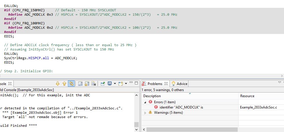
#if (CPU_FRQ_150MHZ) // Default - 150 MHz SYSCLKOUT
#define ADC_MODCLK 0x3 // HSPCLK = SYSCLKOUT/2*ADC_MODCLK2 = 150/(2*3) = 25.0 MHz
#endif
#if (CPU_FRQ_100MHZ)
#define ADC_MODCLK 0x2 // HSPCLK = SYSCLKOUT/2*ADC_MODCLK2 = 100/(2*2) = 25.0 MHz
#endif
#define ADC_CKPS 0x1 // ADC module clock = HSPCLK/2*ADC_CKPS = 25.0MHz/(1*2) = 12.5MHz
#define ADC_SHCLK 0xf // S/H width in ADC module periods = 16 ADC clocks
#define AVG 1000 // Average sample limit
#define ZOFFSET 0x00 // Average Zero offset
#define BUF_SIZE 2048 // Sample buffer size
// Global variable for this example
Uint16 SampleTable[BUF_SIZE];
main()
{
Uint16 i;
AdcRegs.ADCTRL2.all=0x0000;
AdcRegs.ADCTRL2.bit.RST_SEQ1 = 0x1;
AdcRegs.ADCTRL2.bit.RST_SEQ2 = 0x1;
AdcRegs.ADCMAXCONV.all= 1;
/* ADC Config */
AdcRegs.ADCTRL1.all=0x8050;
AdcRegs.ADCTRL3.all = 0x00E0;
AdcRegs.ADCTRL2.bit.SOC_SEQ1 = 1;
/* SEQ1 Config */
AdcRegs.ADCTRL2.bit.INT_ENA_SEQ1 = 1;
AdcRegs.ADCCHSELSEQ1.bit.CONV00 = 0;
for (i=0; i<BUF_SIZE; i++)
{
SampleTable[i] = 0;
}
// Start SEQ1
AdcRegs.ADCTRL2.all = 0x2000;
// Take ADC data and log the in SampleTable array
for(;;)
{
for (i=0; i<AVG; i++)
{
while (AdcRegs.ADCST.bit.INT_SEQ1== 0) {} // Wait for interrupt
AdcRegs.ADCST.bit.INT_SEQ1_CLR = 1;
SampleTable[i] =((AdcRegs.ADCRESULT0>>4) );
}
}
}