This thread has been locked.

If you have a related question, please click the "Ask a related question" button in the top right corner. The newly created question will be automatically linked to this question.

Ls parameter identification go wrong

Other Parts Discussed in Thread: DRV8301

I have bought LVSERVOMTR  (Teknic M-2310P-LN-04K) and DRV8301-69M-KIT  . Control characteristics are alright by evaluating.

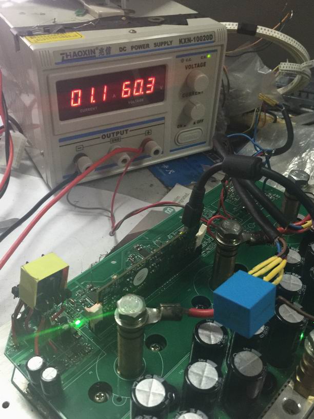
Then I designed my circuit board by reference to DRV8301-69M-KIT  .

I need more output current to diver MOSFET,so I use IR2114.I used hall current sensor which range is 40A  to do three-phase current measurement.

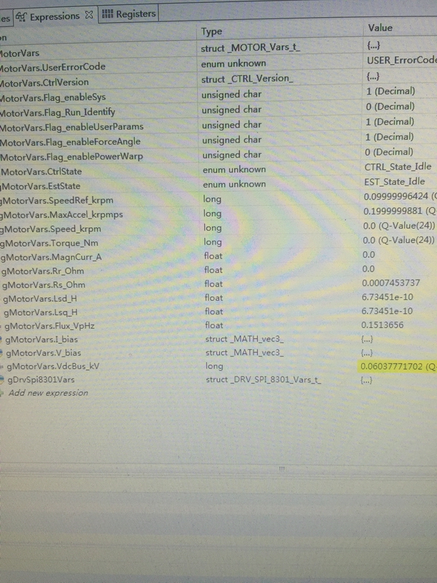
When I used my board to run lab02b,I got Rs = 2.xxx but Ls_q and Ls_d = 6.xxx *e-10. I think it was wrong result.

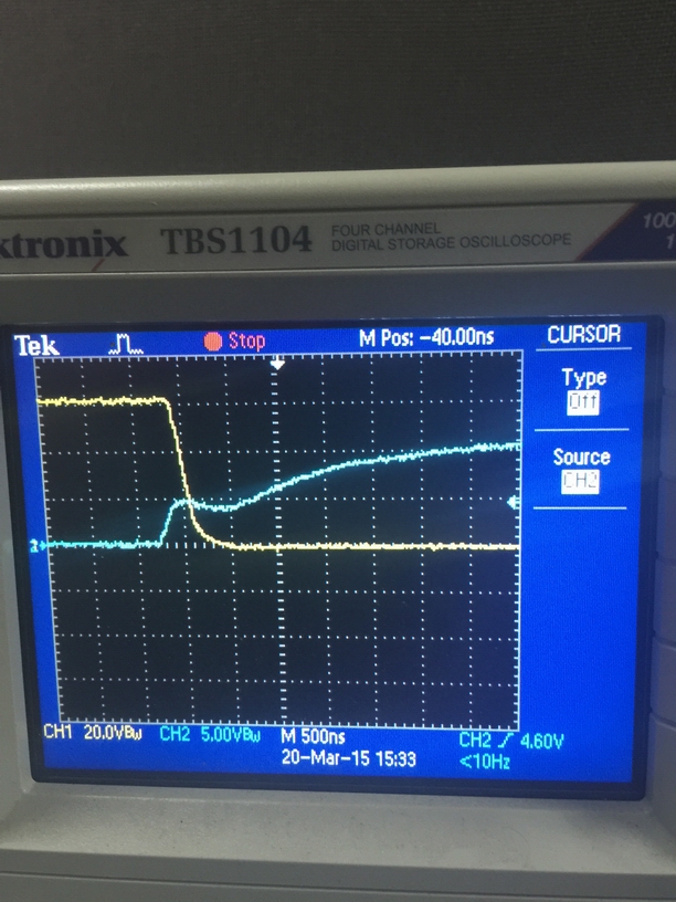
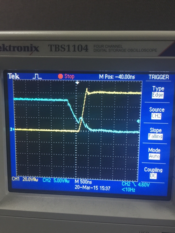
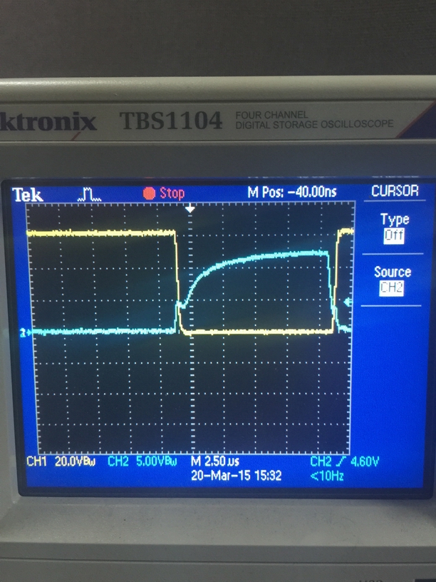
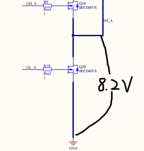
Now I confirm polarity of the current feedback is correct.I found each of the phases voltage to ground was 8.1V when the code did not perform but ti was 0.8V on DRV8301-69M-KIT . can it lead to the wrong  parameter identification results? Or there are other mistakes?

USE.H:2061.user.h

Schematic:https://e2e.ti.com/cfs-file/__key/communityserver-discussions-components-files/171/Schematic.7z

  • you say you need more output current but in user.h you actually set the current to a LOWER value of (80.0). Why?
    Are you actually using a hall current sensor on all three phases or just two? If two, are you just using U and V?
    #define USER_NUM_CURRENT_SENSORS (3)
    did your voltage measurement pole change? you left it the same.
    #define USER_VOLTAGE_FILTER_POLE_Hz (335.648)


    You may have some HW issues...it's really hard to help you debug those over the forum.
    But you certainly have some SW issues. Please review chapter 5 of SPRUHJ1 and set your user.h correctly
  • hi

    I ask some another questions:

    1.Did the code of lab13e suit for velocity control of PMSM with encoder? I found lab13e cound not make motor run immediately because of initial Rs detection.How to make motor run immediately ?

    2.we know J10 is used to connect  five signal wires of HALL sensor on DRV8301-69M-KIT  ,but how to modify the program if I make five signal wires of encoder J10 on my board? Thanks.

  • you say you need more output current but in user.h you actually set the current to a LOWER value of (80.0). Why?

    Now I only use this hall current sensor measurement Teknic M-2310P-LN-04K,I will use A greater range sensor to measurement  a high powered motor in the future.

    Are you actually using a hall current sensor on all three phases or just two?

    I used three sensors,One phase one sensor.

    did your voltage measurement pole change?

    as follows,I did not change the value of resistances and capacitance,so I did not change the FILTER_POLE.Am I right?


  • correct on you pole, since you didn't change your voltage circuit.

    I don't understand what you have done with your hall current sensors. I suspect you have made a mistake on the scaling somehow.
  • Thanks so much for response...

    I know hall current sensor,I used it before to measure current.

    Its bandwidth is DC~30KHz

    Power supply is 5V

    Its output voltage is 2.5V when no current flow through circuit.

    Its output voltage is 4.5V when 32A current flow through circuit.

    Its output voltage is 0.5V when -32A current flow through circuit.

    to get 0~3.3V voltage range,I used three resistors to shrink this scale,then connected the I/O Port by a voltage follower.

    The actual measurement results were 1.645V 1.658V and 1.632V,when no current flow through circuit.

  • for +/- 32A you should use
    #define USER_IQ_FULL_SCALE_CURRENT_A (32.0)
    #define USER_ADC_FULL_SCALE_CURRENT_A (64.0)
  • Hi Chris, I am following this thread due I am getting also wrong value on Rs Ls.

    I am using Launchpad F28027F and DRV8301 BP, target an ACIM not low voltage so I am experimenting this motor before to make my HV board, I measured with an LCR meter both Ls and Rs they are in the order of 42Ohm and 20mH, when I run software this identify about 9 Ohm and 0 for Ls, motor don't get identified and don't spin too.

    Are these parameter from what I read on chapter 5 6 of guide be close to measured value or are to be estimated another way?

    If user.h parameter are not ok motor never spin so I quitted experiment reading manual but still I am not able identify where measurement error come.

    Are some simple criteria to have a user.h fast tuned?

    Chapter 5 6 of user guide appear as a first but number I see are confusing and I am thinking also remove motor and insert a 3PHases reactive load to impose value, can be  this a good idea or not?

    Next week can be get the low voltage ACIM but till not arrive have at hand just 230/400V.

    how are to be used value from panel of lab02b to tune ACIM motor?

  • Hello,Chris.

    Ls identification was still incorrect,although I had done according what you said.

    At last,I found the reason,but I can not explain this phenomenon:

    Through some experiments, I found my sensors,peripheral hardware circuit and software programs did not have a big problem these days.

    Then I tried to change the bootstrap capacitor value from 15uF to 0.47uF,I found Ls was more like the correct result by identification.

    Look at experimental results:

    First,I used DRV8301-69M-KIT to identify the motor parameters:

    Second,I used my board with 0.47uF bootstrap capacitor to identify the motor parameters:

    Third,I used my board with 15uF bootstrap capacitor to identify the motor parameters(I got a incorrect value):

    Now I have two questions:

    1.I doubt  the bootstrap capacitor value influence FAST algorithm ,but I do not know why?

    2.I think it is enough I use 0.47uF bootstrap capacitor on the board with six MOSFETs,if I only identify and run the Teknic M-2310P-LN-04K motor.But in a practical application,I need to design a circuit board which can bear 400A current (48V).So I need to use many MOSFETs in parallel.That means I have to use a large bootstrap capacitor (>= 10uF).If a bootstrap capacitor value influence FAST algorithm,then how to do solve the problem in high power application?

  • Robert,
    You can't run a high voltage ACI using a LP+BP. You aren't able to produce enough voltage on the phases for any sort of proper operation to put it into a state where you can ID the parameters. You need to be able to apply rated voltage to induce the proper fields.
  • Who can give me some advice on the matter?
  • I've sent this on to some other people to see if they can comment.
  • Chao,

    The recommended bootstrap capacitance is 0.1uF +/-20%. Values greater than this could have negative effects on the device. Most likely the DRV8301 is not functioning properly with the larger bootstrap capacitor which is why the motor does not ID.

  • ChrisClearman said:
    You can't run a high voltage ACI using a LP+BP. You aren't able to produce enough voltage on the phases for any sort of proper operation to put it into a state where you can ID the parameters. You need to be able to apply rated voltage to induce the proper fields

     Hi Chris, I am just trying understand parameters, before ACIM I checked a low voltage SMPM, this one again report 9 Ohm but measured Rs and Ls are completely different, motor spin but low speed are not regular nor high speed start get out of phase then shut down by security system due to excessive vibration and phase current.

     Are Ls measured from current slope?  Rs by current at saturation or from evaluation of L/R time constant?

     How can I insert these value and just confirm they are series inductance and resistance of inductor when rotor is locked. Can I use an LCR meter or some different criteria must be applied?

     About ACIM, yes I know cannot spin full speed but I usually use low voltage to teach class about slip and rotor reaction, I am not sure what parameter in Instaspin mean and if different from electrical machinery theory similar name parameter.

  • have you read any of SPRUHJ1 ?
    sections 4.6 through chapter 6 would be helpful to review
  • Hello Nicholas

    I think it is enough I use 0.1uF +/-20% bootstrap capacitor on the board with six MOSFETs,if I only identify and run the Teknic M-2310P-LN-04K motor.
    But in a practical application,I need to design a circuit board which can bear 400A current (48V).So I need to use many MOSFETs in parallel.Qg of MOSFET is larger.That means I have to use a large bootstrap capacitor (>= 10uF).0.1uF bootstrap capacitor can not make MOSFETs work appropriately,

    And not only that,Drv8301 is not fit for the application of heavy power,its Io is too small,so I used IR2114 as gate driver IC.

    If a bootstrap capacitor value influence FAST algorithm,then how to do solve the problem in high power application?Does that mean Instaspin technology is only  fit for the application of low power?

  • Chao,

    Yes, there is a limitation of the gate driver in how much Qg it can drive and at what frequency. This is not a limitation from FAST. FAST does not care what power stage is connected to it. The two main limiting factors are the gate drive supply regulator and bootstrap capacitor. The GVDD charge pump can support up to 30mA (Idcload ~= Fsw * #MOSFETs_SWITCHING * Qg) .I believe you will hit this limitation before the bootstrap capacitor becomes an issues. The other limitation is how much inrush current to the bootstrap capacitor the DRV8301 can support. This leads to the 0.1uF specification.

    The DRV8301 was targeted at 100A and below applications. Unfortunately it is our strongest gate driver at the moment.

  • Maybe I did not express myself clearly.I did not use Drv8301 as gate driver IC.I used IR2114 as gate driver IC on my board(I had uploaded my schematics before).So the experimental data was nothing to do with Drv8301.I doubt the size of capacitance affects the input signals of FAST (Phase current or back EMF ) ,But so far I still didn’t know how capacitance affects input signals?If I know fault principle,then I am able to try find some schemes to solve this problem in large power application.
  • Chao,

    I see, I am unfortunately unfamiliar with that driver. I would suggest checking that the output signals (on the half-bridges) are matching the inputs signals (from the MCU) during the ID phase and seeing if the driver is functioning correctly. Seems that most likely some error is happening with the gate driver.

  • ChrisClearman said:
    have you read any of SPRUHJ1 ?

     Hi Chris, thank for pointing to precise section but  yes I read chapter on identification and parameter too less than Inertia I planned use after all primary variable are fully understood.

    ChrisClearman said:
    sections 4.6 through chapter 6 would be helpful to review

     Section 4.6 is addressing User.h values, I read also section 6 that is more close to what I am seeking for.

     From that section I can infer a sine current is injected and I suppose one of two classical methd are used:

     a> two PWM drive phases windings are identical to have the Rs Ls measurement across one and two in parallel windings (3/2R measured)

    b> one phase get open to measure across two winding in series (2R measured).

     From that current I suppose voltage is measured and phase relation evaluated then by impedance modulus both reactive and resistive term are evaluated from?

     please can you confirm which method is used by instaspin?

     I wait have time to experiment with low voltage ACIM motor is now arrived  to do some more close evaluation and see why don't match LCR measure then I can build high voltage interface.

  • Roberto,
    I can't comment further on the details beyond what is documented in SPRUHJ1
  • I used IR2114 and 2.2uF bootstrap capacitor,set PWM Frequency = 10K.It just became normal,I can get correct values.But I have one question about input power.
    Under no load condition,I run the motor(Teknic M-2310P-LN-04K).The bus current was 100mA,when I used six MOSETs.But the bus current was 900mA,when I used 30 MOSFETs.
    I don't understand why so large power consumption was produced.Do you think the bus current is too great from your experience?Is it normal?

  • I would expect there to be about 5x the current used, so 900mA seems high, but I don't have enough experience to know if this is an issue.

    glad to see you solved the main issue with a HW change!

  • chao yang said:
    Under no load condition,I run the motor(Teknic M-2310P-LN-04K).The bus current was 100mA,when I used six MOSETs

    Hi Chao, on this condition all seems regular so

    chao yang said:
    But the bus current was 900mA,when I used 30 MOSFETs.

     You accounted here some more loss, how are MOS connected? I don't know IR2114 but some basic rule to isolate issue:

     Can you post some waveform from your circuits?

     In particular on one leg of drivers measure gate drive voltage at both resistor sides (this evaluate gate current too)

    If you have a current sensor then measure current on Source of low side MOS, HIGH side is fine too with same voltage of phase.

     Voltage on output phase and current flowing from

    If you own a differential probe measure the Gate voltage of upper MOS correlated to LOW side Gate.

     In advance try just raise dead time.

  • Hello chris

    I think I am in serious trouble,although I have already solved the problem about bootstrap capacitor.

    A new problem has appeared:

    When I run the lab02b with my power board which contains 6 mosfets,Rs = 0.32~0.33,Ls_q = Ls_d = 0.00017~0.00018. These values are correct.

    When I run the lab02b with my power board which contains 48 mosfets,Rs and Ls ware incorrect,and the bus current was 1.1A!(When I disconnect the motor from my board,it was still 1.1A ).

    So I found When mosfet was increased,parameter identification was affected and power losses was huge!

    I did not know when some mosfets in parallel,what went wrong.

    Some experimental figure,When I run the lab02b with my power board which contains 48 mosfets:

    Completely wrong parameters:

    A huge loss:

    Vgs and Vds of the upper mosfet (A phase),PWM rising edge:

    Vgs and Vds of the upper mosfet (A phase),PWM failling edge:

    Vgs and Vds of the upper mosfet (A phase),the full figure:

  • I'm not sure how I can help you debug this issue. There certainly seems to be something incorrect with the HW.