Hi all,
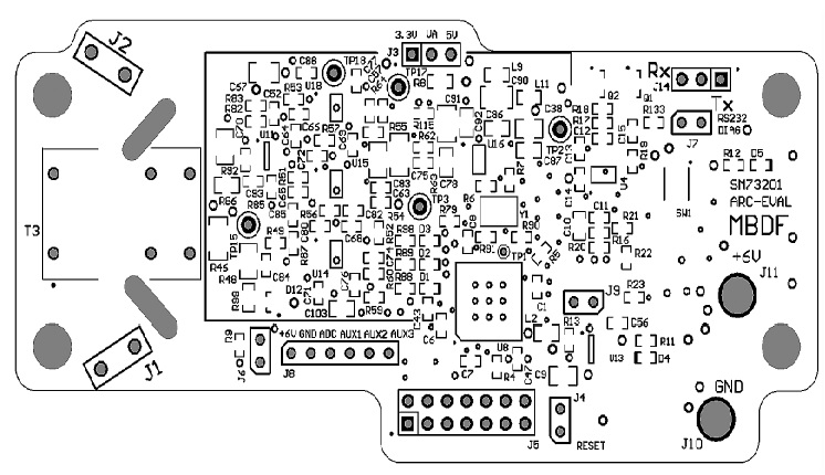
I was working on my RD-195 Arc Eval board recently. I powered it by a 6V voltage source (from DC power supply) and the current is around 0.1-0.2A (don't exactly remember). I used "+6V" and "GND" pin on J8 for powering. Today I moved the board and I reconnect it to the power supply afterwards, the power supply suddenly changed from "Constant Voltage" mode to "Constant Current". The output current of DC power supply remained at 0.2A and the voltage at 2V. This shift is completed automatically on my DC power supply when output current is larger than 0.2A. I raised the current limit and when the current limit reached up to 1A, output voltage reached 6V. The board temperature increased rapidly and I cut the power. However the board can not function properly. When I was testing whether there's short circuit on the board, I found there're several resistor value don't match the datasheet.
R9: 0.8K ohm (should be 20K ohm)
R10: 5.3K ohm (should be 10K ohm)
R82, R83: 6K ohm (should be 10K ohm)
R92: 40K ohm (should be 1M ohm)
I also found that the board I have is little bit different from the PCB layout shown in the datasheet (i.e. J9 on my board with J7 on PCB layout), so I wonder whether these values are right? Are they correct because RD-195 I have is a different version from the one in datasheet, or it means I burned those resistors somehow?
Also, I don't have the all the peripheral circuit schematic so I don't know where are those resistors connected to and do they have any thing to do with the hardware failure. The only schematic information I know are "Analog Front End", "Reference Voltage", "Self Test Circuit", "A/D Converter" given in the application report. Can somebody give me the overall circuit schematic that conclude every component on the board?
Any help is appreciated, thank you!
Hezi