This thread has been locked.

If you have a related question, please click the "Ask a related question" button in the top right corner. The newly created question will be automatically linked to this question.

enquire of RS232 interface in C2000 AC/DC Developer's Kit

Hello,

Now, I am doing some test on TMS320C2000 AC/DC Developer's Kit.

I got a question on I/O interface.

What does the interfaces of I/O-INT_RS232-RX and I/O-INT_RS232-TX mean?

Is this RS232 the SCI-A? Or other serial port communication?

Thanks.

Yeqin

  • Hi Yeqin,

    Yeqin Wang said:
    Is this RS232 the SCI-A? Or other serial port communication?

    Yes, this would SCIA serial to usb through FTDI chip. You can observe a COM port in the Device Manager once you insert the kit.


    Regards,

    Gautam

  • Hi Gautam,

    I am sorry, I do not fully understant your answer.
    I want to use a central controller to comunicate with TMS320C2000 AC/DC Developer's Kit throgh RS232.
    I just need to program SCIA port in TMS320C2808 in my software. Does it correct?

    Thanks.

    Best Regards,
    Yeqin
  • Hello Yeqin, 

    I couldn't find the schematic of this kit but I think YES, you only need to program your MCU to have serial port communication.

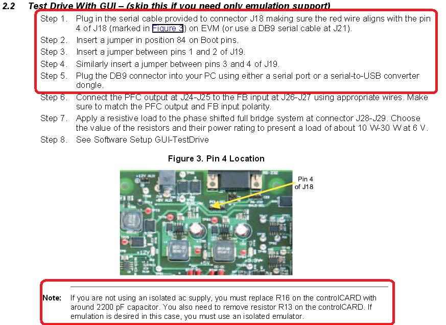
    Please be careful with the hardware setting (or you may damage your controlcard or your kit), that I found in the QSG:

    Good luck!

    Best regards,

    Maria

  • Hi Gautam,

    Thank you for your reply.
    I followed your instranctions. Yes the comunication is OK now. The data type for RS232 comunication is only uint8. If I want to sent a uint16 date. I need to change this uint16 date to two uint8 date. I usually did in this way. Does get another method to sent a uint16 directly?

    But, I got a proble today. I use my own control algorithm to test on DCDC part. However, I think I broke the Mosfets.
    The conditions are below:
    1. I disabled the AC/DC part. The PFC part did not work.
    2. I gave 5V low voltage.
    3. I also gave 48V high Voltage. (I used a power supply, the current limitaion was 1A)
    4. The load was 2ohm Resistance.
    Then, I wrote a open loop software, the PWM frequency is 200Khz, the phase shift angle is set 250. the duty cycle of PWM is set 10%.
    Then I download the software in RAM. When I started to run the program. Then system collapsed. (Power supply changed into current limit mode with almost zero voltage).
    I checked board later. I found the mosfets in both upper arm bridge and lower arm bridge is punctured (the resistance is almost 0).

    I cannot figer out what is going on. As the limit of Mosfet is 100V 36V. My condition is only 48V 1A, far below the limit of Mosfet.
    Do you get any idea on this?
    Do you get any thoughts to avoide this?

    I will purchase new mosfet and do test angain. I need to find what is going on on this first.

    Thank you.

    best regards,
    yeqin
  • Hi Gautam,

    I have checked that the broken Mosfets are Q5 and Q6.
    I have set about 8% dead band for upper and lower Mosfets. I think the problem is not on short circle directly.

    Thanks.

    Yeqin
  • Hi Gautam,

    Here is another thing that this is no puncture trace in appearance of Q5 and Q6. The appearance like new.

    Yeqin
  • Yeqin Wang said:
    I cannot figer out what is going on. As the limit of Mosfet is 100V 36V. My condition is only 48V 1A, far below the limit of Mosfet.
    Do you get any idea on this?
    Do you get any thoughts to avoide this?

    I would like you to probe the drain to source voltage to check for any voltage spike. This looks the reason for their failure.

  • Hi Gautam,

    The DC power supplier is linear power supply. I am sure it does not have voltage spikes.
    By the way, if the Mosfet is punctured by spike voltage. Does it not get some puncture trace on apperance and sometimes with big "explosive sound"?

    Thanks.
    Yeqin
  • Some sound should be there but lot many times there's no sound and the device looks perfect! You're sure that MOSFET has been damaged right? Also, what is the gate resistance? Does it go with MOSFET datasheet?

    Regards,
    Gautam
  • Yes. I am sure about that. the resistance of both GS and DS is close to zero. I have looked MOSFET datasheet. The broken ones are abnormal.

    Thanks.

    Yeqin.
  • We can only replace them and monitor the DS pulses. Place snubbers if required. Also, did you ever try loading the program while the board was running at high power?