This thread has been locked.

If you have a related question, please click the "Ask a related question" button in the top right corner. The newly created question will be automatically linked to this question.

SPI initialization code

Guru**** 163035 points

Other Parts Discussed in Thread: CONTROLSUITE

I am posting this on behalf of a customer who is looking for assistance with SPI initialization.

In looking at the generated assembly for the SPI loopback example in controlSUITE there was something odd seen in the code.

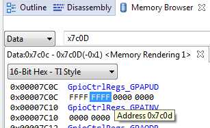
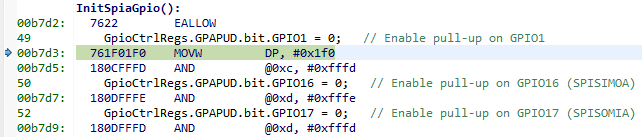
In the assembler code in _InitSpiGpio it sets the DP register MOVW DP,#_GpioCtrlRegs+13 which equals 0x00007C0D hex.

If you look in the F2837xD technical reference manual on page 997 in GPIO_CTRL_REGS Registers there is no 00007C0D register.

You have to remember that we're assembler coders and we directly use the hardware registers.

Can you please let me know what register 00007C0D is or is their another manual we should be looking at instead of the Technical Reference Manual - SPRUhm8b

  • John,

    While the C28x is a 32-bit  CPU, the registers are 16-bit addressable. All 32-bit registers are aligned to even addresses. The example code is using bitfield accesses, and the compiler breaks this down into the necessary 16-bit accesses. If they look at the memory window in 16-bit config, 0x7C0D is visible.

    This is a screen capture from the memory window:

    Also here is the Disassembly window. You can see that when enabling the pull-up on GPIO1 (the same register) the address will be in the lower 16-bits of the register, leading to an access to 0x7C0C. The next line enables the pull-up on GPIO16, which is in the upper 16-bits of the register located at address 0x7C0D.

    I would recommend they check out the TMS320C28x CPU and Instruction Set Reference Guide for more information if they have not already. 

    Regards,

    Mark