This thread has been locked.

If you have a related question, please click the "Ask a related question" button in the top right corner. The newly created question will be automatically linked to this question.

Problem with lab 5e

Other Parts Discussed in Thread: MOTORWARE, TMDSHVMTRINSPIN, TMS320F28069M, CONTROLSUITE

Hello,


I'm having some trouble running motorware lab 5e. I have a high voltage kit (TMDSHVMTRINSPIN) with a TMS320F28069M control card and I need to control the speed of a treadmill without and encoder.

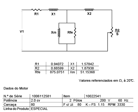
I've already updated my motor parameters according to the data provided by my supplier as you can see in the image attached and I calculated these values based on section 4.8 from user's guide.

So I bypassed labs 2, 4, 5a and 5b and did the inertia identification process from lab 5c. So far so good.

Then I moved on to lab 5e and adjusted the bandwidth gain and went to test the sensorless control, but I'm not having the expected result.

It is relatively easy to stop the rotation of the motor by putting more weight pressing with my foot while I'm on the treadmill. I saw a video showing the results of the control with Instaspin Motion and its far from what it shows.


I noticed a saturation on the Iq_Ref_A followed by the stop of the motor when I applied my weight like in the video. So I tried increasing the USER_MOTOR_MAX_CURRENT parameter to compensate that. But when setting these parameter to 8 A or higher I lose complete control of the motor when applying load and the motor stops. Is it because of some hardware protection in the kit? My motor rated currrent is 6A and its rated speed is 3330 rpm.

Am I doing something wrong / missing something? Can I expect to solve my control problem using this lab? My user.h file is attached as well.

Thanks in advance for the help.

Vitor.
7848.8322.user.h

  • Vitor,

    You mentioned that you bypassed lab 2.  I would recommend that you go back and run that lab.  Motor datasheets are often off by 10-20% and with sensorless control this difference can be critical.

    My advice would be to run lab 02a in order to get your motor parameters before trying the speed control in lab 05e.

  • Hi Adam,

    I expressed myself badly. Initially I did the labs 2 to 5e but since it didn't work I asked for my supplier for the datasheet parameters.

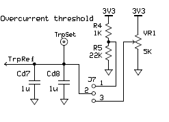
    I discovered something that improved greatly the response of the kit. I changed the TripRef of the kit by changing the position on the MAIN-J7 jumper, placing it in the middle pin and the left pin (toward control card) and adjusted the trimpot to set the voltage to 3.3V.

    In the kit, however, it instructed to place such jumper in the middle pin and the right pin (towards capacitors).

    After doing so, I could set the USER_MOTOR_MAX_CURRENT parameter to 8A and higher without causing the system to stop, unlike before and got much more torque when applying load. 

    I tried the sensorless control with the parameters from the datasheet and from the identification process from lab 2a, but didn't notice any difference.

    Is there a limit to the max current I can set to my motor without damaging the kit? What is the maximum current value the kit can provide?

    Vitor.

  • Vitor,

    The kit is rated for 1.5kW, so if you are running at 300V I wouldn't push it past 5A.  Another option is to reduce the magnetizing current, this will allow more current to be used producing torque instead of creating the magnetic field.

  • Hello Adam,

    Thanks again for the response. I tried using the suggested 5A current and reducing the magnetizing current, but the resulting torque is just too weak. Is there a way for me to check the current value on each phase, like reading a project parameter value or something? Is the variable Iq_Ref_A the value of current actually provided from the kit to the motor or is it just a value of current used in the project calculations?

    Could I get the values of the parameters in the project adjusted for the 4cv, 220V motor showed in the video of "Instaspin Motion in Action: Treadmill" to compare with mine? Here is the video link:

    www.ti.com/.../watch.tsp
  • Vitor,

    You should be able to get the current value on each phase from the software. The ADC results are stored in: gAdcData

    I don't seem to have the software that we used with that customer anymore. I can't seem to find it where I store that information.

    When we did that test with the customer, the overcurrent protections were not yet in place in the kit. So you can remove that jumper so that it allows you to push more current but you are risking damaging the kit in the process.

    The other thing to consider is that your motor is rated for a higher power level than the kit and maybe you need to design your own hardware to be able to get the full torque producing capabilities of your motor.

    But with the reference design you can still test out the sensorless control in terms of speed range, just not in terms of power range.
  • Hi Adam,

    Thanks for all the help. I think I got the response I wanted with the hardware limitations of the kit.
    I'll try to design my own hardware and see if anything changes.

    One last thing. I was looking at the PFC macroblock and searched for projects in Motorware and ControlSuite that used this macro, but couldn't find anything. Is there a project in specific that configures and utilizes this macro? Or is just making the connections on the board sufficient?

    Thanks.

    Vitor.
  • Vitor,

    I've never used the PFC block on the HV Kit.  You might have better success asking about it over at: 

    That forum focuses on the motor drivers and I bet they would be better able to answer your question.

  • Thanks Adam.
    I'll ask about it there.
    Thanks again for all the help.

    Vitor