This thread has been locked.

If you have a related question, please click the "Ask a related question" button in the top right corner. The newly created question will be automatically linked to this question.

problem of judging the completion of ADC sampling by EOCx INT pulse

hi,

I am learning the piccolo series DSC with F28069 and working on the ADC temperature sensor conversion functions.

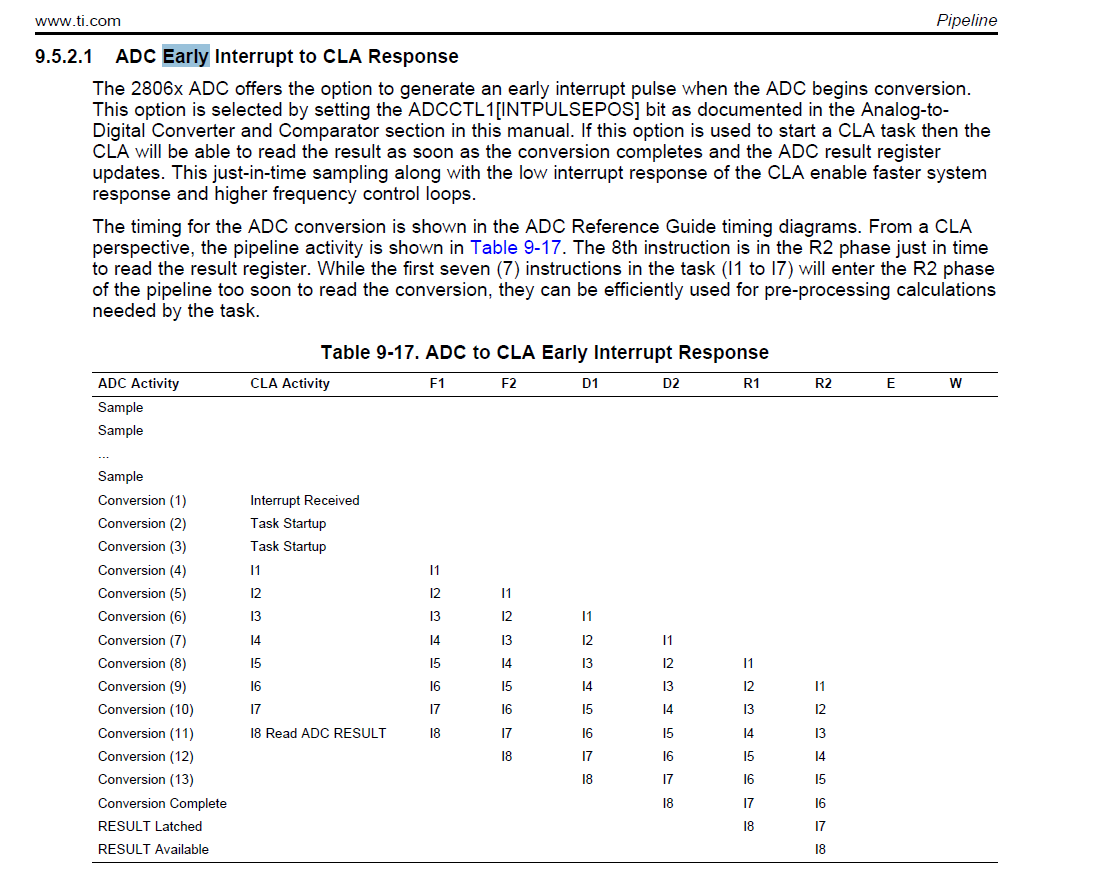
In the example, the completion of ADC sampling is judged by EOCx INT pulse and as shown below.

       //Wait for end of conversion.
       while(AdcRegs.ADCINTFLG.bit.ADCINT1 == 0){}  //Wait for ADCINT1
       AdcRegs.ADCINTFLGCLR.bit.ADCINT1 = 1;        //Clear ADCINT1

But I looked at the ADC timing and found that the int pulse occurs much earlier than the point that the result is latched.

So how can I make sure that the result I read from AdcResult register is correct?

I know the timing of pipelining may solve my puzzle but I can not find useful materials.

I am looking forward to your kind help.

thanks and regards

Di

  • Di,

    The diagram that you referenced is for the EARLY interrupt pulse, which fires before the conversion has completed. This is intended for applications with tight timing requirements where the result needs to be read as soon as possible.

    After the S/H window is complete, the ADC takes a fixed number of cycles to convert the S/H voltage. In the diagram, it shows 14 cycles for the ADC conversion to be ready in the results register after the interrupt pulse fires. The application would need to make sure that the result is not read until at least 14 cycles after receiving the interrupt pulse.

    For applications with looser timing requirements, you can use the LATE interrupt pulse, which fires after the ADC result has been updated.

    -Tommy

  • Tommy,

    Thanks for your reply.

    As you said,  for the EARLY interrupt pulse, which fires before the conversion has completed. INT pulse generation occurs when ADC begins conversion (neg edge of sample pulse od the sampled signal).

    It should be used for the application with tight timing but can it guarantee the result is latched by the code example?

           //Wait for end of conversion.
           while(AdcRegs.ADCINTFLG.bit.ADCINT1 == 0){}  //Wait for ADCINT1
           AdcRegs.ADCINTFLGCLR.bit.ADCINT1 = 1;        //Clear ADCINT1
    

    I referred to the CLA chapter and there is something about the ADC Early Interrupt to CLA Response. Then I know CLA can get the correct ADC result.

    Does the C28x pipeline is the same with the CLA pipeline?

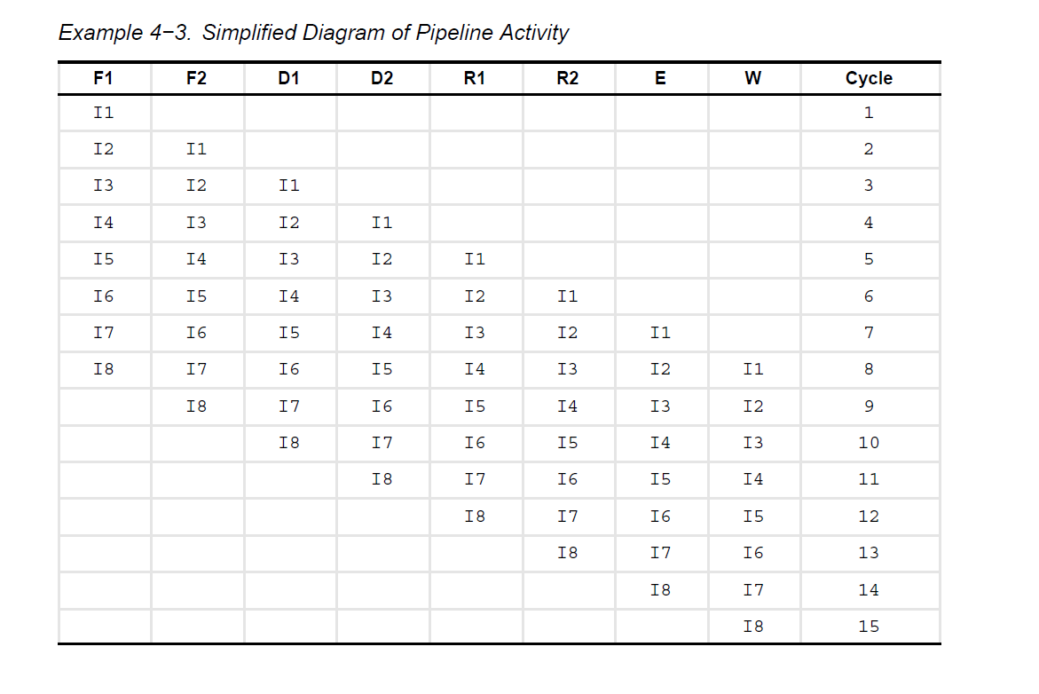
    In the TMS320C28x Extended Instruction Sets Technical Reference Manual there is a figure about the C28x pipeline, it seems just the same as the CLA pipeline.

    So can I just think they are the same and I can make sure that the result I read is a correct one?

    -Di

  • Di,

    No, they are not the same. There is no hardware mechanism in place to guarantee that the ADC conversion is latched into the result register when your application responds to the early interrupt. Only the late interrupt can guarantee this.

    If you use the early interrupt, you must ensure that your software execution has sufficient cycles of separation between the early interrupt and reading of the ADC result.

    -Tommy
  • Tommy,

    Thanks a lot.

     In TI's example it just use this early INT pulse to judge the conversion and the early INT pulse is designed as that. I guess that function may work well.

    I want to learn something about the C28x pipeline to find the exact timing. And where can I get the C28x pipeline reference?

    I have worked on this problem for days and I want to totally solve it.

    Do you have some materials about the C28x pipeline? And what's the differences between the C28x pipeline and the CLA pipeline ?

    Thanks again for your kind help!

    : )


    -Di

  • Di,

    You can reference the C28x Instruction Set Reference Guide (www.ti.com/.../spru430) and the F2803x CLA Reference Guide (www.ti.com/.../spruge6b.pdf). The CLA core design should be the same between F2803x and F2806x.

    -Tommy
  • Sorry to bother you again.

    I looked up the  C28x Instruction Set Reference Guide and found the Simplified Diagram of Pipeline Activity.

    Here it is.

      It seems just the same as the CLA pipeline.

    So can you tell me the differences between the two pipelines? I don't know how to find it.

    Thanks again for your kind help! I appreciate a lot for what you have teached me!

    -Di

  • Di,

    I am not familiar enough with the processor architectures to answer your question with confidence. I would recommend that you start a new post with this question so that you attract the attention of the right experts.

    My understanding is that the CLA was derived from the C28x processor design so I would not be surprised to see a lot of similarities.

    -Tommy