Other Parts Discussed in Thread: TMDSDOCK28335, TMS320F28335, MAX3221
Hello TI-community,
I'm a beginner in DSP programming and need your help for solving my problem.
At first I want to describe my hardware and software setting.
Hardware
I use an experimenter board (TMDSDOCK28335). It consists of a docking station and a controlCard F28335. The complete docking station is powered by USB by a PC.
The manual can be found here.
http://www.ti.com/lit/zip/sprc675
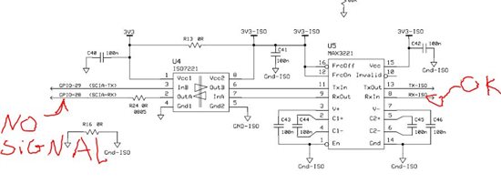
In file "USBDockingStation_Schematic [R3].pdf" you can find the circuit diagram of the docking station.
A low resolution figure of the schematic of the docking station can be found here.
Attention!
I change the docking station hardware. The connection jumper J9 is closed now.
Software
For the DSP F28335 I use Code Composer Studio 3.3. I found an example code for SCI communication and I changed it for solving my problem.
On the PC I write a test application in Microsoft Visual Studio 2005.
What do I want?
The docking station has got a FTDI chip. This chip (FT2232D) has a connection to the DSP F28335. The circuit diagram can be seen in the schematic of the docking station. The red rectangle symbolizes the FTDI FT2232D. The FTDI has got two channels. ChannelA is for programming the DSP via JTAG. ChannelB is connected to GPIO28 and GPIO29 of the DSP. These two ports belong to SCI-A interface of the DSP.
I want a bidirectional communication between my PC and the DSP F28335 by using the SCI-A interface. My test application for the PC uses a DLL for the FTDI chip. My Code Composer Code project activates the SCI-A, but I have a problem with the Interrupt Service Routine of SCIRX-A. Therefore I use an oscilloscope to plot the electrical signal on the ports GPO28 and GPIO29. The Interrupt Service Routine for SCITX-A works fine. The communication from the DSP to the PC works perfectly, but the signals from the PC to the DSP were not executed.
The following picture shows the electrical signal on port GPIO28 (blue graph) and GPIO29 (orange graph).

The electrical signal never becomes Boolean false! I cannot explain that. Therefore I remove my jumper at J9 and I measure the output signal of the FTDI. The following picture shows the output signal of the FTDI2232D.

It works fine.
My problem
I want to control the DSP with my PC test application, but the signals of the PC are not executed by the DSP. I think the error has to do with DSP port GPIO28 (SCIRX-A) because its signal never becomes Boolean false. The voltage never becomes 0V, so the interrupt SCIRX-A never occur.
My first idea was to disable the internal pull up for GPIO28. I add command
GpioCtrlRegs.GPAPUD.bit.GPIO28 = 1;
but it does not work.
What is wrong with my hardware?
Is there any mistake in my CCS project? Wrong setting of the GPIO's? Wrong initial sequence of the ports?
Please help me. Thanks in advance!
Steffen
Here my CCS project:
// Original by
// Lab9_2: TMS320F28335
// (c) Frank Bormann
//
// DSP sends the string "The 28335-UART is fine !" every 2 seconds
// CPU Timer0 ISR every 50 ms
// SCI-Setup: 9600 Baud, 8 Bit , ODD Parity , 1 Stopbit
// SCI - TX - Interrupt used in this Lab
// Watchdog active , serviced in ISR and main-loop
//###########################################################################
#include "DSP2833x_Device.h"
// External Function prototypes
extern void InitSysCtrl(void);
extern void InitPieCtrl(void);
extern void InitPieVectTable(void);
extern void InitCpuTimers(void);
extern void ConfigCpuTimer(struct CPUTIMER_VARS *, float, float);
// Prototype statements for functions found within this file.
void Gpio_select(void);
void SCIA_init(void);
interrupt void cpu_timer0_isr(void); // Prototype for Timer 0 Interrupt Service Routine
interrupt void SCIA_TX_isr(void); // SCI-A Transmit Interrupt Service
//SL
interrupt void SCIA_RX_isr(void);
// Global Variables
char message[]={"The F28335 - UART ISR is fine ! # "};
int index =0; // index variable into message
//###########################################################################
// main code
//###########################################################################
void main(void)
{
InitSysCtrl(); // Basic Core Initialization
// SYSCLK=150MHz, HISPCLK=75MHz, LSPCLK=37.5MHz
EALLOW;
SysCtrlRegs.WDCR= 0x00AF; // Re-enable the watchdog
EDIS; // 0x00E8 to disable the Watchdog , Prescaler = 1
// 0x00AF to NOT disable the Watchdog, Prescaler = 64
Gpio_select(); // GPIO9, GPIO11, GPIO34 and GPIO49 as output
// to 4 LEDs at Peripheral Explorer
InitPieCtrl(); // default status of PIE; in DSP2833x_PieCtrl.c
InitPieVectTable(); // init PIE vector table; in DSP2833x_PieVect.c
// re-map PIE - entry for Timer 0 Interrupt and SCI-A-TX
EALLOW;
PieVectTable.TINT0 = &cpu_timer0_isr;
PieVectTable.SCITXINTA = &SCIA_TX_isr;
//SL
PieVectTable.SCIRXINTA=&SCIA_RX_isr;
EDIS;
InitCpuTimers(); // Function in: DSP2833x_CpuTimers.c
// Configure CPU-Timer 0 to interrupt every 50 ms:
// 150MHz CPU Freq, 50000 µseconds interrupt period
ConfigCpuTimer(&CpuTimer0, 150, 50000); // DSP2833x_CpuTimers.c
SCIA_init(); // Initalize SCI
PieCtrlRegs.PIEIER1.bit.INTx7 = 1; // Cpu Timer 0 isr
PieCtrlRegs.PIEIER9.bit.INTx2 = 1; // SCI-A-TX-isr
//SL
PieCtrlRegs.PIEIER9.bit.INTx1=1;
// Enable the PIE.
PieCtrlRegs.PIECTRL.bit.ENPIE = 1;
// Enable CPU INT1 (CPU-Timer 0) and INT9 (SCIA-TX):
IER = 0x101;
// Enable global Interrupts and higher priority real-time debug events:
EINT; // Enable Global interrupt INTM
ERTM; // Enable Global realtime interrupt DBGM
CpuTimer0Regs.TCR.bit.TSS = 0; // Start T0
while(1)
{
SciaRegs.SCITXBUF=message[index++]; // send first character
while(CpuTimer0.InterruptCount < 40) // 40 * 50ms = 2 sec
{
EALLOW;
SysCtrlRegs.WDKEY = 0xAA; // Service watchdog #2
EDIS;
}
index =0;
CpuTimer0.InterruptCount = 0;
}
}
void Gpio_select(void)
{
EALLOW;
GpioCtrlRegs.GPAMUX1.all = 0; // GPIO15 ... GPIO0 = General Puropse I/O
GpioCtrlRegs.GPAMUX2.all = 0; // GPIO31 ... GPIO16 = General Purpose I/O
GpioCtrlRegs.GPAMUX2.bit.GPIO28 = 1; // SCIRXDA
GpioCtrlRegs.GPAMUX2.bit.GPIO29 = 1; // SCITXDA
GpioCtrlRegs.GPBMUX1.all = 0; // GPIO47 ... GPIO32 = General Purpose I/O
GpioCtrlRegs.GPBMUX2.all = 0; // GPIO63 ... GPIO48 = General Purpose I/O
GpioCtrlRegs.GPCMUX1.all = 0; // GPIO79 ... GPIO64 = General Purpose I/O
GpioCtrlRegs.GPCMUX2.all = 0; // GPIO87 ... GPIO80 = General Purpose I/O
GpioCtrlRegs.GPADIR.all = 0;
GpioCtrlRegs.GPADIR.bit.GPIO9 = 1; // peripheral explorer: LED LD1 at GPIO9
GpioCtrlRegs.GPADIR.bit.GPIO11 = 1; // peripheral explorer: LED LD2 at GPIO11
GpioCtrlRegs.GPBDIR.all = 0; // GPIO63-32 as inputs
GpioCtrlRegs.GPBDIR.bit.GPIO34 = 1; // peripheral explorer: LED LD3 at GPIO34
GpioCtrlRegs.GPBDIR.bit.GPIO49 = 1; // peripheral explorer: LED LD4 at GPIO49
GpioCtrlRegs.GPCDIR.all = 0; // GPIO87-64 as inputs
//SL
// GpioCtrlRegs.GPAPUD.bit.GPIO28=0;
GpioCtrlRegs.GPAPUD.bit.GPIO28 = 1; // Disable internal pullup on GPIO28
// GPIO-28 - PIN FUNCTION = SCI-RX
// GpioCtrlRegs.GPAMUX2.bit.GPIO28 = 1; // 0=GPIO, 1=SCIRX-A, 2=Resv, 3=Resv
// GpioCtrlRegs.GPADIR.bit.GPIO28 = 0; // 1=OUTput, 0=INput
// GpioDataRegs.GPACLEAR.bit.GPIO28 = 1; // uncomment if --> Set Low initially
// GpioDataRegs.GPASET.bit.GPIO28 = 1; // uncomment if --> Set High initially
EDIS;
}
void SCIA_init()
{
SciaRegs.SCICCR.all =0x0027; // 1 stop bit, No loopback
// ODD parity,8 char bits,
// async mode, idle-line protocol
SciaRegs.SCICTL1.all =0x0003; // enable TX, RX, internal SCICLK,
// Disable RX ERR, SLEEP, TXWAKE
// SYSCLOCKOUT = 150MHz; LSPCLK = 1/4 = 37.5 MHz
// BRR = (LSPCLK / (9600 x 8)) -1
// BRR = 487 gives 9605 Baud
SciaRegs.SCIHBAUD = 487 >> 8; // Highbyte
SciaRegs.SCILBAUD = 487 & 0x00FF; // Lowbyte
SciaRegs.SCICTL2.bit.TXINTENA = 1; // enable SCI-A Tx-ISR
//SL
SciaRegs.SCICTL2.bit.RXBKINTENA=1; //enable SCI-A Rx-ISR
SciaRegs.SCICTL1.all = 0x0023; // Relinquish SCI from Reset
}
interrupt void cpu_timer0_isr(void)
{
CpuTimer0.InterruptCount++; // increment time counter
GpioDataRegs.GPBTOGGLE.bit.GPIO34 = 1; // toggle LED at GPIO34
// Service the watchdog every Timer 0 interrupt
EALLOW;
SysCtrlRegs.WDKEY = 0x55; // Service watchdog #1
EDIS;
// Acknowledge this interrupt to receive more interrupts from group 1
PieCtrlRegs.PIEACK.all = PIEACK_GROUP1;
}
interrupt void SCIA_TX_isr(void) // SCI-A Transmit Interrupt Service
{
// test for end of string ('\0'); if not, send next character
if (message[index]!= '\0' ) SciaRegs.SCITXBUF= message[index++];
// Acknowledge this interrupt to receive more interrupts from group 9
PieCtrlRegs.PIEACK.all = PIEACK_GROUP9;
}
///////////////////////////////////////////////////////////////////////////////////////////
interrupt void SCIA_RX_isr(void)
{
Uint16 i=0;
//if this interrup occur, the message has to be change
char msg[]={"Interrupt RX was here ! # "};
//overwrite message with new msg
for(i=0; i<sizeof(msg); i++)
message[i]=msg[i];
i++;
message[i]='\0';
// Acknowledge this interrupt to receive more interrupts from group 9
PieCtrlRegs.PIEACK.all = PIEACK_GROUP9;
}
//===========================================================================
// End of SourceCode.
//===========================================================================