This thread has been locked.

If you have a related question, please click the "Ask a related question" button in the top right corner. The newly created question will be automatically linked to this question.

F28027F debug error -1135

Other Parts Discussed in Thread: MOTORWARE, BOOSTXL-DRV8301, CCSTUDIO, CONTROLSUITE, TMS320F28027, LAUNCHXL-F28027F

Dear,

I have just received my C2000 Piccolo Launcpad: LaunchXL - F28027F and my Booster pack BOOSTXL-DRV8301. I have installed CCStudio, GUI Composer and MotorWare. Currently I am trying to debug one of the examples provided in MotorWare and upload it to the board before I start trying to write my own code.

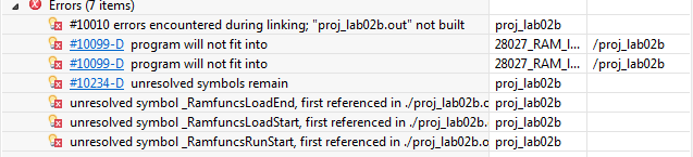
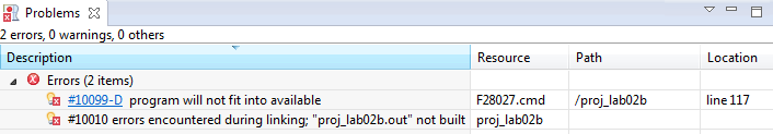
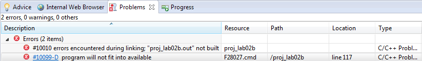
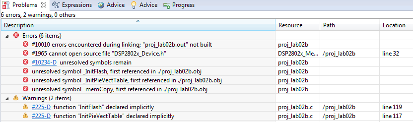
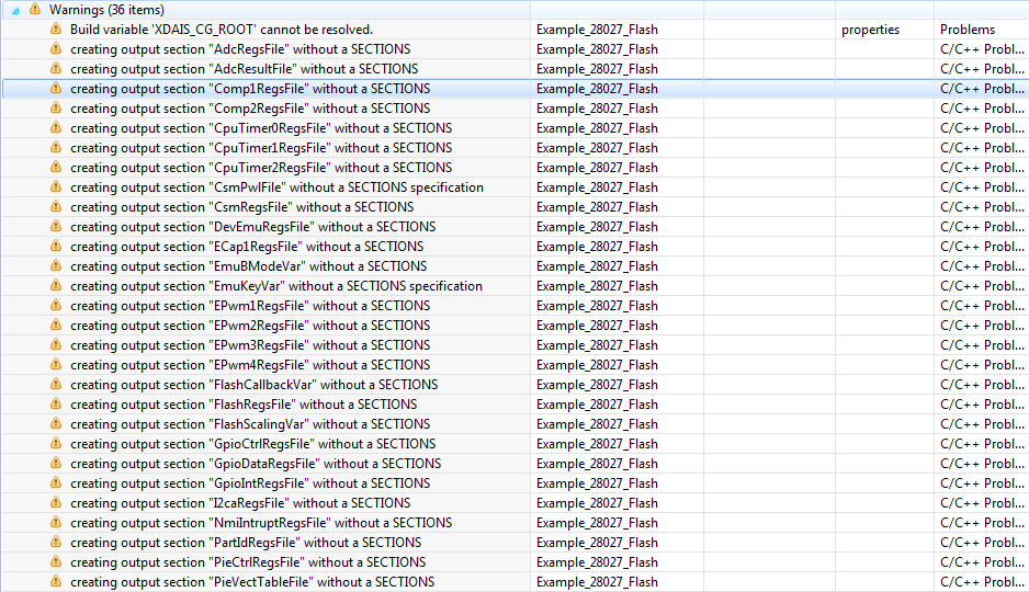
The thing is that everytime I try to debug the Code I get the following error:

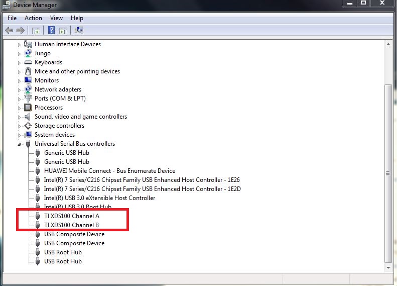
"C28xx: Error connecting to the target: (Error -1135 @ 0x0) The debug probe reported an error. Confirm debug probe configuration and connections, reset the debug probe, and retry the operation. (Emulation package 5.1.641.0) "

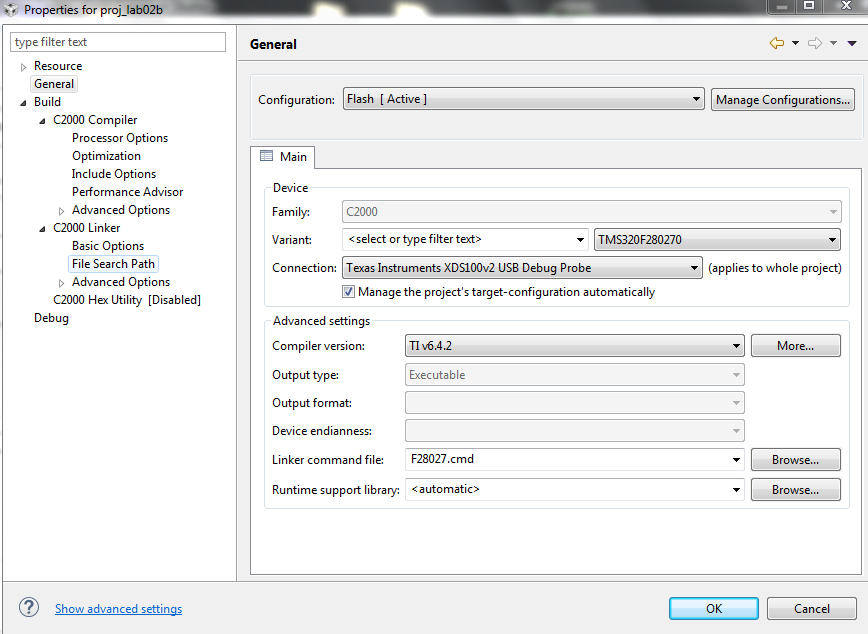
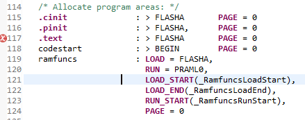
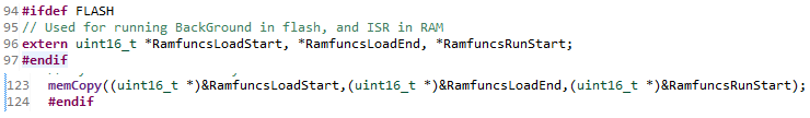
How can I resolve this? These are my project settings, which I believe to be correct.

 (Sorry if this isn't formatted correctly, my internet is really slow)

Thanks in advance,

Michiel

  • Hi Mike,

    Can you check the boot switches at S1? Are they properly set ie in ON position?

    Regards,
    Gautam
  • Hi Gautam,

    I can confirm that all the switches are set in the On position.

    Regards,
    Michiel
  • Did you try replacing the data-cable? Also, are the drivers installed properly? Please check your device manager, you should be able to see 2 channels A&B:

    Regards,

    Gautam

  • That should be in order aswell, I will check this next Tuesday since my hardware is still at the campus and I won't be there until then. Already thanks for your help!

    Kind regards,
    Michiel
  • No problem. Keep us informed.

    Regards,
    Gautam
  • Yes I can see both channels on my device manager!

    These errors also pop up on the problems tab, if they can be of any use to you.

  • The .cmd file seems to be RAM based and not Flash based. Can you try with F28027.cmd that can be found here:
    C:\ti\controlSUITE\device_support\f2802x\v129\DSP2802x_common\cmd
    ie check with flash configuration

    Regards,
    Gautam
  • Appearantly I don't have controlsuite yet, getting it now!
  • Okay So I didn't find control Suite on my PC but I did find the F28027.cmd in the drop down menu under linker command file. I tried this without success though. Do I still need to change this somewhere else?

    The errors however have been reduced to just 2, aside from the one "Error: -1135" stated in my first post. I am still not able to connect to the debug probe.

  • Okay so I did some more digging and in this: https://e2e.ti.com/support/microcontrollers/c2000/f/902/t/398617 thread I realised that there is indeed a difference between the LaunchXL - F28027 and the F28027F. I never really thought that this was the case since there was never an option in any of the menu's to select the F28027F as shown below.

    Could this be my problem? And If so, how can I get the F28027F to show up in the menu's? Or is this neglectible?

    Also included a picture of the box to make clear what exact type of board I have.

  • Hi Mike,

    Could this be my problem? And If so, how can I get the F28027F to show up in the menu's? Or is this neglectible?

    F28027 device selection is correct for F28027F too. Yes, in the previous post you'd selected the wrong device which you corrected later.
    Do does it build well?

    Regards,
    Gautam
  • No, it is not building correctly. If this was the case I would have posted that. I installed controlsuite and used the Linker file you mentioned earlier. I am still getting these errors, which link through to the code above. Do you have any idea how I can get rid of this? I really need to get this sorted as fast as I can.

  • Here are the detailed steps to run the program from flash:
    You need to add these two statements

    MemCopy(&RamfuncsLoadStart, &RamfuncsLoadEnd, &RamfuncsRunStart);
    InitFlash(); after InitPieVectTable();

    Add DSP2802x_MemCopy.c file to the project.

    Define extern variables above main() function.

    extern Uint16 RamfuncsLoadStart;
    extern Uint16 RamfuncsLoadEnd;
    extern Uint16 RamfuncsRunStart;

    Replace 28027_RAM_lnk.cmd with F28027.cmd
    Compile the code.
    Configure your GPIO's to boot to flash.

    Regards,
    Gautam
  • All right, will give that a shot in a minute!

    Also, here is what I get when I run "Test Connection" in "Target Configuration". Maybe this clarifies something.

    [Start: Texas Instruments XDS100v2 USB Debug Probe]
    
    Execute the command:
    
    %ccs_base%/common/uscif/dbgjtag -f %boarddatafile% -rv -o -F inform,logfile=yes -S pathlength -S integrity
    
    [Result]
    
    
    -----[Print the board config pathname(s)]------------------------------------
    
    C:\Users\Adept\AppData\Local\TEXASI~1\CCS\
        ti\0\0\BrdDat\testBoard.dat
    
    -----[Print the reset-command software log-file]-----------------------------
    
    This utility has selected a 100- or 510-class product.
    This utility will load the adapter 'jioserdesusb.dll'.
    The library build date was 'Feb 18 2015'.
    The library build time was '23:56:50'.
    The library package version is '5.1.641.0'.
    The library component version is '35.34.40.0'.
    The controller does not use a programmable FPGA.
    The controller has a version number of '4' (0x00000004).
    The controller has an insertion length of '0' (0x00000000).
    This utility will attempt to reset the controller.
    This utility has successfully reset the controller.
    
    -----[Print the reset-command hardware log-file]-----------------------------
    
    The scan-path will be reset by toggling the JTAG TRST signal.
    The controller is the FTDI FT2232 with USB interface.
    The link from controller to target is direct (without cable).
    The software is configured for FTDI FT2232 features.
    The controller cannot monitor the value on the EMU[0] pin.
    The controller cannot monitor the value on the EMU[1] pin.
    The controller cannot control the timing on output pins.
    The controller cannot control the timing on input pins.
    The scan-path link-delay has been set to exactly '0' (0x0000).
    
    -----[The log-file for the JTAG TCLK output generated from the PLL]----------
    
    There is no hardware for programming the JTAG TCLK frequency.
    
    -----[Measure the source and frequency of the final JTAG TCLKR input]--------
    
    There is no hardware for measuring the JTAG TCLK frequency.
    
    -----[Perform the standard path-length test on the JTAG IR and DR]-----------
    
    This path-length test uses blocks of 512 32-bit words.
    
    The test for the JTAG IR instruction path-length failed.
    The JTAG IR instruction scan-path is stuck-at-ones.
    
    The test for the JTAG DR bypass path-length failed.
    The JTAG DR bypass scan-path is stuck-at-ones.
    
    -----[Perform the Integrity scan-test on the JTAG IR]------------------------
    
    This test will use blocks of 512 32-bit words.
    This test will be applied just once.
    
    Do a test using 0xFFFFFFFF.
    Scan tests: 1, skipped: 0, failed: 0
    Do a test using 0x00000000.
    Test 2 Word 0: scanned out 0x00000000 and scanned in 0xFFFFFFFF.
    Test 2 Word 1: scanned out 0x00000000 and scanned in 0xFFFFFFFF.
    Test 2 Word 2: scanned out 0x00000000 and scanned in 0xFFFFFFFF.
    Test 2 Word 3: scanned out 0x00000000 and scanned in 0xFFFFFFFF.
    Test 2 Word 4: scanned out 0x00000000 and scanned in 0xFFFFFFFF.
    Test 2 Word 5: scanned out 0x00000000 and scanned in 0xFFFFFFFF.
    Test 2 Word 6: scanned out 0x00000000 and scanned in 0xFFFFFFFF.
    Test 2 Word 7: scanned out 0x00000000 and scanned in 0xFFFFFFFF.
    The details of the first 8 errors have been provided.
    The utility will now report only the count of failed tests.
    Scan tests: 2, skipped: 0, failed: 1
    Do a test using 0xFE03E0E2.
    Scan tests: 3, skipped: 0, failed: 2
    Do a test using 0x01FC1F1D.
    Scan tests: 4, skipped: 0, failed: 3
    Do a test using 0x5533CCAA.
    Scan tests: 5, skipped: 0, failed: 4
    Do a test using 0xAACC3355.
    Scan tests: 6, skipped: 0, failed: 5
    Some of the values were corrupted - 83.3 percent.
    
    The JTAG IR Integrity scan-test has failed.
    
    -----[Perform the Integrity scan-test on the JTAG DR]------------------------
    
    This test will use blocks of 512 32-bit words.
    This test will be applied just once.
    
    Do a test using 0xFFFFFFFF.
    Scan tests: 1, skipped: 0, failed: 0
    Do a test using 0x00000000.
    Test 2 Word 0: scanned out 0x00000000 and scanned in 0xFFFFFFFF.
    Test 2 Word 1: scanned out 0x00000000 and scanned in 0xFFFFFFFF.
    Test 2 Word 2: scanned out 0x00000000 and scanned in 0xFFFFFFFF.
    Test 2 Word 3: scanned out 0x00000000 and scanned in 0xFFFFFFFF.
    Test 2 Word 4: scanned out 0x00000000 and scanned in 0xFFFFFFFF.
    Test 2 Word 5: scanned out 0x00000000 and scanned in 0xFFFFFFFF.
    Test 2 Word 6: scanned out 0x00000000 and scanned in 0xFFFFFFFF.
    Test 2 Word 7: scanned out 0x00000000 and scanned in 0xFFFFFFFF.
    The details of the first 8 errors have been provided.
    The utility will now report only the count of failed tests.
    Scan tests: 2, skipped: 0, failed: 1
    Do a test using 0xFE03E0E2.
    Scan tests: 3, skipped: 0, failed: 2
    Do a test using 0x01FC1F1D.
    Scan tests: 4, skipped: 0, failed: 3
    Do a test using 0x5533CCAA.
    Scan tests: 5, skipped: 0, failed: 4
    Do a test using 0xAACC3355.
    Scan tests: 6, skipped: 0, failed: 5
    Some of the values were corrupted - 83.3 percent.
    
    The JTAG DR Integrity scan-test has failed.
    
    [End: Texas Instruments XDS100v2 USB Debug Probe]

  • Do work on the above steps... share your results. If still you've the issues... we'll check with the above issue.

    Regards,
    Gautam
  • Alright, but where do I need to add that code? In what file?
  • main.c (or the main c file)
    I would like you to refer this sample example: C:\ti\controlSUITE\device_support\f2802x\v129\DSP2802x_examples_ccsv4\flash_f28027
  • A part of the code you are proposing is already present in this form, should I just leave it as it is or should I replace it with your version?

  • These are the errors I get after working out your suggestion, I left the code which was already in place (as shown above) since it seemed to me that this did the same.

    I'm sorry to keep bothering you with this. I really need to get this figured out and I don't know where else to go :/

  • I would like you to follow this example code: C:\ti\controlSUITE\device_support\f2802x\v129\DSP2802x_examples_ccsv4\flash_f28027

    Regards,
    Gautam
  • Oh okay, first time I just opened the .c file in Visual studio, didn't really teach me all that much. Imported the project into CCS now, things are looking way more detailed. Will give this a good read and report back after trying again.
  • Gautam,
    I think I recall I faced similar problems when trying to load code when I accidentally ordered the 'F' variant from Farnell some time ago. My recall of the issue at the time is not the best but maybe because the devices have Insta-SPIN FOC preloaded, the device's have less available memory??
    As I say I don't recall fully, and I was not using MotorWare, so my past issue may be completely irrelevant but I thought maybe my 2 cents may help ! :)
    T

  • Gautam,

    I am still reading through all the code of the example and the PDF provided with it. This has given me a bit more insight in the situation.
    Still, I tried to build & debug the example project to see if this would work without problems. I got no errors while building but while Debugging I still got the initial error I made this Thread for (-1135, debug probe error, unable to connect to target)
  • Try replacing the data cable...
  • Tried that several times. Also tried different computers, different usb ports.. I just can't seem to get anything on the microcontroller.
  • Finally... one last thing that I could suggest is check the voltage levels on your board and compare them with your schematic. Esp. the JTAG connections. Refer C2000 launchpad schematics for detailed JTAG connections.
  • I am going to try and measure it with a DMM, but the connections on the JTAG emulator are way too small to acctually measure. Also if it really wasnt working, should it still be possible to be detected on the device manager of my pc? the 'power' led is also still bright red
  • Being a launchpad the connections should be fine... Mike can you contact a FAE/distributor near your place to get the launchpad replaced?

    Regards,
    Gautam
  • I don't know, I'm currently residing in South Africa and I ordered the launchpad directly from TI in the US..

    Would you mind going over the basic setup instructions with me one last time to make sure that I didn't do anything wrong or misunderstood anything from the included guides / pdf's? Because they can be a bit vague from time to time.

  • Sure, why not!
    Launchpad's S1 & S4 -> ON Position
    Import this project:
    C:\ti\controlSUITE\device_support\f2802x\v129\DSP2802x_examples_ccsv4\flash_f28027

    Target configuration -> XDS100v2 and TMS320F28027
    Build and then try Debugging. Let me know what you observe.

    Regards,
    Gautam
  • When assigning the target configuration I get these warnings.

    After building I got all these warnings, no idea where they came from.

    And after debugging I got this error, which has been my problem all along.

    The switches are configured correctly, the launchpad is on an is showing in the device manager. I just don't get it.

  • I hope you've CCS v6+ right? Also, which folder is your CCS and controlSuite are installed?

    Generally it should be: C:\ti\ccsv6  &  C:\ti\controlSUITE

    There seems to be a lot of linking issues. Can you try replacing this cmd file to your project: F28027.zip

    Regards,

    Gautam

  • Yes I am using CCS V 6.1. They are installed in said folders.
    Tried using that cmd file already, no success. Also tried with the other one you linked, no more warnings but still getting the same error I've always had "Error connecting to the target etc.."
  • I also tried running a "Test Connection" This has given me the same results as the one I posted earlier.
    If you go back a page then it should be somewhere in the thread. It seemed to fail all the time but I didn't really understand it good enough to make something out of it. Maybe you can.

    Again, thanks for all the help!
  • Yes, for that you can check this link once: processors.wiki.ti.com/.../XDS100
  • I've already checked there and I can't seem to find anything that describes my problem. I think that I'm just going to contact a distributor in SA and order a new one..
  • Hello,
    Can you capture your LP ? I want to check the setup of your hardware. Thanks!
    The project labs from Motorware should be able to be compiled with no error without any modification.

    Best regards,
    Maria
  • I'm sorry but what do you mean with 'capturing my LP?'. And yeah I was expecting the examples to run smoothly aswell but they aren't.. But nothing really is so it clearly is an error at my end

  • Hello,

    What I mean is to take a photo of your LP and upload it here so we can also check whether there is missing HW setting.

    I am also wondering whether this is your first CCS to use. Maybe there is some missing installation when you install CCS.

  • Okay I will do this tomorrow. And yes it's my first time using CCS. Although I have no idea what I could be missing

  • This is my setup, I have tried alot of different variations on this so honestly I'd be amazed if that was the problem.

    http://imgur.com/ZfNAjzR

  • Hey Mike, all the switches are in the wrong position!
    Can you please toggle them to ON position and check?

    Regards,
    Gautam
  • Gautam,

    It might not be all to clear in the picture due to contrast but they are definitely all in the ON position.
    There is ON written on the switches with an arrow next to it pointing in the right direction which they are set in.

    Just for the sake of it I switched them all from position and I got the same result as always.
  • Yup, contrast issue :)

    One suggestion, can you go through these instructions:8446.C2000_launchpad_basics.pdf

    Try using a new workspace.

    Regards,

    Gautam

  • Already went through that PDF and tried new workspaces aswell
  • Mike... it seems you've tried everything! Replacing cable to the above step by step implementation.
    Anyway you can get your board replaced ?
  • I've already ordered a new board last friday, I don't have the time to wait for a replacement. In all the rush I also accidentally ordered a LaunchpadXL F28027 instead of a F28027F, I mailed to get that order canceled last friday aswell but I havent got any confirmation yet. So I'm probably going to receive one of both somewhere this week :/
  • OK. Keep us informed.

    Goodluck & Regards,
    Gautam
  • Hello,

    Your jumper JP1 and JP3 for 3.3 and 5V are in wrong position. Please fix them (horizontal based on the picture) and you can run your debugger.

    Best regards,

    Maria

  • Nice catch Maria :)