Hi,
I am learning the piccolo series DSC with F28069 and have tried different ways to trigger the ADC SOCx.
Firstly, I used the timer1 as the trigger and it worked well.
Then I want to use the ADCINT1 as the trigger to make a continuous stream of conversions.
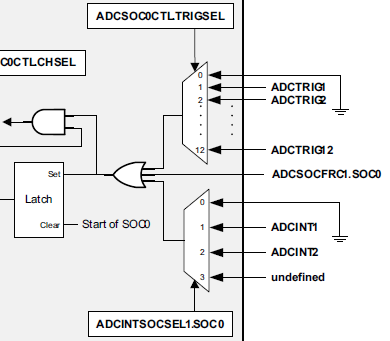
In the guide it says the setting of ADCINTSOCSEL1 will override the TRIGSEL field in the ADCSOCxCTL register, so I just add some code to my previous project as shown below.
void ConfigAdc(void)
{
	EALLOW;
	AdcRegs.ADCCTL2.bit.ADCNONOVERLAP = 1;	//Enable non-overlap mode
	AdcRegs.ADCCTL1.bit.INTPULSEPOS	= 1;	//ADCINT1 trips after AdcResults latch

	AdcRegs.ADCSOC0CTL.all=0x1006;			// 这条指令与下面3条指令等价
	//AdcRegs.ADCSOC0CTL.bit.CHSEL 	= 0;		// 设置 SOC0 选择 ADCINA0
	//AdcRegs.ADCSOC0CTL.bit.TRIGSEL = 2;		// 触发源为CPUTimer1
	//AdcRegs.ADCSOC0CTL.bit.ACQPS 	= 6;		// 设置SOC0的采样/保持窗为7个ADC时钟周期 (7 = ACQPS + 1)
	AdcRegs.ADCSOC1CTL.all=0x1046;			// SOC1 选择 ADCINA1,触发源为CPUTimer1,ACQPS = 6
	AdcRegs.ADCSOC2CTL.all=0x1086;			// SOC2 选择 ADCINA2,触发源为CPUTimer1,ACQPS = 6
	AdcRegs.ADCSOC3CTL.all=0x10C6;			// SOC3 选择 ADCINA3,触发源为CPUTimer1,ACQPS = 6
	AdcRegs.ADCSOC4CTL.all=0x1106;			// SOC4 选择 ADCINA4,触发源为CPUTimer1,ACQPS = 6
	AdcRegs.ADCSOC5CTL.all=0x1146;			// SOC5 选择 ADCINA5,触发源为CPUTimer1,ACQPS = 6
	AdcRegs.ADCSOC6CTL.all=0x1186;			// SOC6 选择 ADCINA6,触发源为CPUTimer1,ACQPS = 6
	AdcRegs.ADCSOC7CTL.all=0x11C6;			// SOC7 选择 ADCINA7,触发源为CPUTimer1,ACQPS = 6

	AdcRegs.ADCINTSOCSEL1.bit.SOC0 = 1;    //ADCINT1 will trigger SOCx. TRIGSEL field is ignored
	AdcRegs.ADCINTSOCSEL1.bit.SOC1 = 1;
	AdcRegs.ADCINTSOCSEL1.bit.SOC2 = 1;
	AdcRegs.ADCINTSOCSEL1.bit.SOC3 = 1;
	AdcRegs.ADCINTSOCSEL1.bit.SOC4 = 1;
	AdcRegs.ADCINTSOCSEL1.bit.SOC5 = 1;
	AdcRegs.ADCINTSOCSEL1.bit.SOC6 = 1;
	AdcRegs.ADCINTSOCSEL1.bit.SOC7 = 1;

	AdcRegs.INTSEL1N2.bit.INT1SEL	= 7;	//setup EOC7 to trigger ADCINT1 to fire
	AdcRegs.INTSEL1N2.bit.INT1CONT  = 0;	//Disable ADCINT1 Continuous mode
	AdcRegs.INTSEL1N2.bit.INT1E     = 1;	//Enabled ADCINT1
	EDIS;

	EALLOW;  // This is needed to write to EALLOW protected register
	PieVectTable.ADCINT1 = &adc_isr;
	EDIS;    // This is needed to disable write to EALLOW protected registers
}
And the configuration of timer1 is as shown below.
void ConfigTimer(void)
{
	InitCpuTimers();
	ConfigCpuTimer(&CpuTimer1,90,1000000);

	EALLOW;  // This is needed to write to EALLOW protected registers
	PieVectTable.TINT1 = &cpu_timer1_isr;
	EDIS;    // This is needed to disable write to EALLOW protected registers

	CpuTimer1Regs.TCR.bit.TSS = 0;    //start the timer1

}
At first I thought the ADC will not work for the ADCINT1 trigger could not occur and I should force the EOC7 to start by ADCSOCFRC1 register.
However I ran the project and the ADC ISR counter increased.
Then I tried to stop the timer1 by commenting out the
//CpuTimer1Regs.TCR.bit.TSS = 0; //start the timer1
and the ADC ISR counter remained as zero.
So is there something wrong with my configuration ? I don't know how the timer1 triggered the ADC SOC.
I put my whole project as the attachment.
I am looking forward to your kind help.
thanks and regards
Di