This thread has been locked.

If you have a related question, please click the "Ask a related question" button in the top right corner. The newly created question will be automatically linked to this question.

Making an E-bike using InstaSPIN FOC

Other Parts Discussed in Thread: MOTORWARE, DRV8301, BOOSTXL-DRV8301, DRV8301-69M-KIT

Now with LAB_5_B project of motorware_14 I can spin my BLDC HUB MOTOR successfully

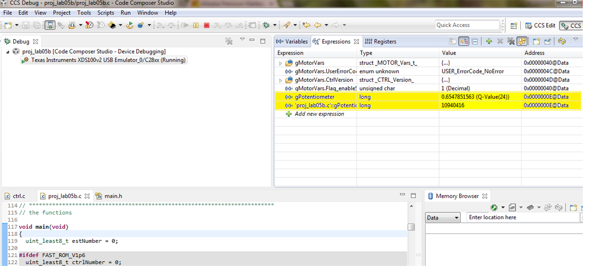
I have also interface potentiometer at ADC_A4 pin to control speed of my motor.(ADC gives me values between 0 to 1 in Q-24 format). following is the intermediate value of my potentiometer  which stored in gPotentiometer variable.

BLDC HUB MOTR IS AS FOLLOWS:

I have connected two potentiometer as follows

(1)  first Potentiometer value stored in variable gPotentiometer and its used to control motor speed.

(2)  second  Potentiometer value stored in variable gPotentiometer1 and its used to enable or disable the (c2000f28027f & DRV BoostXL 8301 )

the value of  first potentiometer is display bellow for having control on motor speed. 

Now with this I can make an E-bike But there is problem occurs with the above logic.

lets assume that motor is running on plane road with speed 200 RPM,now there is slope,,,then while going downside motor speed will increase more that 200 rpm ;;but i am applying 200RPM ,,sooo controller may get damage.

To overcome this problem I should able to switch off the controller while going on slope..ORRR I have to apllly other logic so that controller understand its downslope and its automaticallly switch off itself.

To make  controller off I have made following changes.

for this  I have made changes in the  proj_lab05b.c, in main loop which is as follows::

gPotentiometer1 = HAL_readPotentiometerData1(halHandle);//ADC channel at this pin is kept to either 3.3 v or a 0.00 v

gPotentiometer = HAL_readPotentiometerData(halHandle);

if(EST_isMotorIdentified(obj->estHandle))
{
// set the current ramp
EST_setMaxCurrentSlope_pu(obj->estHandle,gMaxCurrentSlope);
gMotorVars.Flag_MotorIdentified = true;


// set the speed reference

if (gPotentiometer1 >=0.5)

{

gMotorVars.SpeedRef_krpm = gPotentiometer; 
CTRL_setSpd_ref_krpm(ctrlHandle,gMotorVars.SpeedRef_krpm);
}

else

{
 gMotorVars.Flag_enableSys = false;
gMotorVars.Flag_Run_Identify =false;
}

if (gPotentiometer1 >=0)

{
 gMotorVars.Flag_enableSys = true;
gMotorVars.Flag_Run_Identify =true;
}

but  ((  gMotorVars.Flag_enableSys )))flag is not set to true once it gets disable ;;;I have to restart the system again .

what corresponding changes i have to make so that  gMotorVars.Flag_enableSys  flag can set or reset from gPotentiometer1 variable.???


  • I am using C2000F28027f Launchpad and the DRV8301 BOOSTXL drive to control my motor.
    though my motor have 500W,48V rating but I am applying only 24V,6A for test purpose only.
  • at a given frequency this motor bemf will likely produce more than the 26V that the BOOSTXL-DRV8301 can handle.
    regardless of if your controller is "coasting" or not.

    my first suggestion is to create your own HW that fit your motor.
  • Yes you are right ,,creating my own Hardware that fit my motor is my next target towards my e-bike project.
    But now I AM NOT DRIVING MY MOTOR AT RATED RPM (800 ).
    I am just developing program logic (that is making some changes in the LAB_5(B) of motorware_14) for coasting .
    and at initial level i am spinning my motor in between 200 to 300 RPM (only for test purpose.)
    and I have tested motor back emf at these RPM and BEMF is not exceeding above 14 V .
    {{{{ if I am driving my motor at around (600-800 RPM) then c2000f28027f and DRV8301_BoostXL can be damage due to backEMF of motor???}}}}}

    please suggested some corresponding changes in my above logic (or another logic method)so that I can have coasting for my BLDC HUB motor
  • if you are coasting you can't limit the RPM of the motor to insure it doesn't go over some limit.

    if you do implement a coast feature FAST will keep tracking the angle (if you leave it enabled) and you will be able to take control again of the already spinning motor (we call this flying start) but you will need to see the controllers to the proper level so that you don't get a "kick" when you re-enable the PWM outputs
  • has some documentation is available on this flying start implementation method ..
    and can it possible to apply with LAB_5(b) project of MOTORWARE_14 so that I can have flying start
  • there is enough information published in some of the posts on this forum that others have been able to implement the flying start themselves.
    I'm hoping it makes it into MotorWare _15 as an example (late summer).
  • In order to match my (c2000F28027f and DRV8301_BoostXL) requirement I am using another BLDC hub motor

    The rating of this hub motor is as follows::

    250 watt,24 V,10A,800 RPM BLDC  hub  motor.

    I am using Two 12V, 7 Ah battery's to power up the system.

    Now  when I connect the BLDC hub to my bicycle its not even able to generates ENOUGH TORQUE TO PUSH MY BICYCLE FROM STATIONARY POSITION ,UNDER NO LOAD (that is without and driver sitting on bicycle.)

    Motor is drawing 5 A current and starts spinning at very  low speed ; whenever I start my  (c2000F28027f and DRV8301_BoostXL) when Bicycle is in already  running condition with a driver(weight of 60 KG)  is sited on the bicycle.

    I am using LAB_5(b) project example present  in MOTORWARE_2014. 

    please tell me how I can calculate my motor (Mechanical ) torque by using INSTASPIN FOC METHOD, so that I can calculate how much   motor  torque is required to  drive bicycle from stationary condition itself.

    Also tell me whether  I have to use other motorware LAB project (LAB_5(a)=Torque Control Mode) so that motor can generates the maximum torque and its can assist Total bicycle weight of 90 KG.(including bicycle rider).

  • whether I have to  tune my PI controller according to my motor specifications so as to get maximum  motor starting  torque.

    or I have to use LAB_5(A) torque control mode so as to get higher torque.? &

    where I can get the procedure of Tuning of PI controller ?


  • the current control is well set by the motor parameters. you should not have to re-tune.

    full load start-up is a challenging topic, you should read through the forums and SPRUHJ1.

    enable RsRecal
    make sure USER_MOTOR_MAX_CURRENT is sufficiently large (if you are using speed mode) or that your Iq_Ref_A is large enough (torque mode)

    typically ForceAngle needs to be enabled, with proper user.h limits set for your motor

    you will still run into how smoothly this will start-up. The only real way to do this fully sensorlessly with high load and perfectly smooth start-up is to use a salient rotor design and the IPD_HFI feature proj_lab21
  • IS it possible to make and interface a {{{{_48 v Invertor and driver_}}}  just like DRV8301 BOOStXL for runnig a Instaspin FOC .

    some documentation related to this topic is mentioned in somewhere else or not?

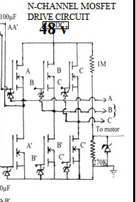
    I have made invertor bridge with (IRF840 N-channel mosfet)as follows, 

    now how  to interface motor pre-driver IC (DRV-8301) with above bridge,so I can spin motor with instaspin FOC.

    please tell me how to make a 48 V,10 A invertor and driver which can connect to c2000F28027F microcontroller.

    I had tried to spin my BLDC hub (48 V ,500W) with applying a  reduced voltage ,but its not giving sufficient torque to drive full load E-bike.

    hence I decided to change my hardware.

  • the DRV8301-69M-KIT is closer to your requirements. it's set-up for +/-40A
    there are some additional TI Designs, but none of them quite meet your needs on the voltage input.
  • so does it mean that I can not make an external invertor bridge that will interface C2000F28027f ?

    I have read somewhere on e2e commnt. that external invertor bridge have made ,,,,but I cant get that exact post..

     do you know documentation about connecting DRV8301 individual  motor drive ic  with the invertor ckt.??

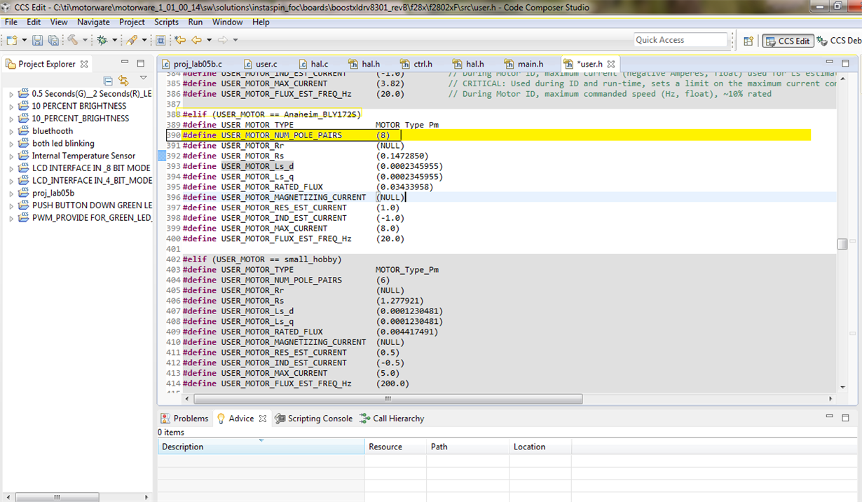
  • my motor have 8 number of pole pairs.

    but motorware_14 lab project   (#elif (USER_MOTOR == Anaheim_BLY172S))   take 4 pole pair as by default value.

    I have made change in the user.h file and make my motor poles as a 8...,, program debug without any error ,,,,,you can see the changes bellow 

    BUT AFTER THIS ,,WHEN i START gui ,,DURING MOTOR IDENTIFICATION PROCESS ITS FAILS AND ERROR OCCURS.

    also my acceleration paddle is made automatically inactive.

    ONLY change that I obsessed is  that motor is spinning at a very high speed (and my ADC channel becomes inactive)

    am  I doing any mistake in this putting motor data.??

    because motor cant be identifield after putting a 10 pole pairs during and spin at higher speed.

    \

  • of course you can make your own inverter and interface it to F28027F MCU.
    most start with the most similar EVM layout and make changes as required.
    a few have even put down a controlCARD or Launchpad header just to make it a little easier initially.
  • you should be setting up your own USER_MOTOR as described in InstaSPIN_labs.pdf

    there is no issue with setting 8 pole pairs, but note that during ID will try to ramp to USER_MOTOR_FLUX_EST_FREQ_Hz
    you have this as 20 Hz, which means with 16 poles this is 150 RPM. That should be in the normal range of this motor, though if it's a bit on the high side you can try reducing to 10 Hz.

    you may need more RES_EST_CURRENT than (1.0) to keep the wheel spinning the whole time. Make sure the wheel is unloaded while you do the test.
  • can you just mentioned (point out ) the material link which explains  "" how to interface user owns invertor bridge with the c2000f28027f "" & "" what care must be taken""

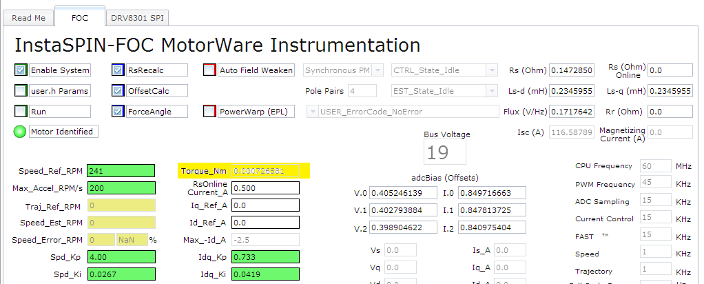
    how you have calculate  TORQUE in the instaspin FOC (it is show in the GUI window as follows)

    I need to find how much torque is given by my motor with having following motor date:

    24 V,10A ,800RPM,

    8-Pole PAIRS

    BLDC hub  motor. 

  • please tell how you have estimated torque  (the formula)  in the instaspin FOC  because;

    I need to find how much torque output is  is given by my motor with using FOC as I dont have any device which can find torque.

     Motor data is as follows:.

    24 V,10A ,800RPM,

    8-Pole PAIRS

    BLDC hub  motor. 

  • you can find this in the projects.

    _iq USER_computeTorque_Nm(CTRL_Handle handle, const _iq torque_Flux_sf, const _iq torque_Ls_sf)
    {
    CTRL_Obj *obj = (CTRL_Obj *)handle;

    _iq Flux_pu = EST_getFlux_pu(obj->estHandle);
    _iq Id_pu = PID_getFbackValue(obj->pidHandle_Id);
    _iq Iq_pu = PID_getFbackValue(obj->pidHandle_Iq);
    _iq Ld_minus_Lq_pu = _IQ30toIQ(EST_getLs_d_pu(obj->estHandle)-EST_getLs_q_pu(obj->estHandle));
    _iq Torque_Flux_Iq_Nm = _IQmpy(_IQmpy(Flux_pu,Iq_pu),torque_Flux_sf);
    _iq Torque_Ls_Id_Iq_Nm = _IQmpy(_IQmpy(_IQmpy(Ld_minus_Lq_pu,Id_pu),Iq_pu),torque_Ls_sf);
    _iq Torque_Nm = Torque_Flux_Iq_Nm + Torque_Ls_Id_Iq_Nm;

    return(Torque_Nm);
    } // end of USER_computeTorque_Nm() function
  • Is it possible to make some hardware changes in the P.C.B. layout of the DRV8301_Boost_XL  pack; so as to make it compatible for working with 48 V supply..

    I think real problem occurs with that BUCK-BOOST convertor which is present on the boost-xl pack. that  needs to be redesign

    or there could be some others problems also..

    I know that  DRV8301-69M-KIT is capable of meeting my requirements but,, If i supposed to make DRV-8301 boosterpack working on 48 V ....Beacause this is what i want.

    can it be possible to make the DRV8301-boostXL Printaded Circuite Board (PCB) with new buck-boost convertor by reffering the component circuit diagram given in hardware files......Because I heard that T.I. is  also provide the design and application data of some boosterpack.??

  • I don't think it's just the converter, I think the bigger limitation is thermals in that footprint. You can't push more power through the PCB. If you look at most e-bike controllers while many are small (some close to a BoosterPack footprint) they will usually have the back of the FETs attached to the aluminum housing for heat dissipation.
  • Yes its true; FET back are attached to aluminium casing for better heat dissipation.

    but as I am  redesign the drv8301 boostxl pcb (keeping rest other component design  of DRV pack same) with wider track width and providing  heat dissipation for FET this problem can be avoided.. BUT now important question is 

    will that PCB work with 48 v having  that new buck-boost convertor.???

    or any other component design configuration of DRV-8301 booster pack ((which is given in the drv8301 hardware file))  I have to change??

    (((__ Sir I want to make whole DRV8301 Booster-pack in my Backyard by making some small modifications in the original DRV8301 Booster-pack circuit connection,, to make it compatible for working with 48 V or above.__))

    Sir... please let me know  whether  some other had made this type of modification before or not ; so that I can refer their post on the e2e community.

  • Hi Sandesh,

    The BoosterPack can be modified for higher voltage but some care most be given.

    The voltage is mainly limited by the capacitor voltage rating and voltage sense resistor dividers.

    The capacitors voltage rating is fixed to 50 V for the bulk capacitor and should not be violated. It is likely in a high power system running at 48 V that you will see the supply bounce over 50 V. It will be difficult to find pin to pin replacements for a higher voltage. You will need to redesign the board with higher voltage components for >50 V.

    The voltage sense resistor dividers can be easily adjusted by modifying the top resistor value.

    The buck regulator and gate drivers of the DRV8301 are fully operational up to 60 V so I do not see a concern their, but care should be taken that the supply voltage does not exceed 60 V for these devices.

  • Thank you  Mr. Nicholas Oborny  for giving yours such a valuable time for clearing my doubts.

    sir can you be more specific on the ""_The capacitors voltage rating is fixed to 50 V for the bulk capacitor and should not be violated_"".

    is it possible  for you to point out which of the components (given in hardware lists of DRV_8301-boostxl) needs to be replaced with higher voltage rating while re-designing of PCB.

    I thinks that, capacitors (with 25v and 50v ) should be replaced  as they have smaller voltage rating.

  • The bulk capacitors are C20 and C21.

    We only need to be concerned with capacitors that are connected directly to high voltage rails. This mainly includes the battery supply input. It appears that the ceramic capacitors on the high voltage rail are already 100V rated.

  • I wanted to know that is it possible to install program in the c2000f28027f microcontroller IC without using the c2000-Launchpad.

    I have spin BLDC motor by using {_C2000F28027f launchpad and DRV8301-boosterpack }

    Now next task is to use only c2000F28027F microcontroller IC without Launchpad ...

    What type of hardware i need to use for programming microcontroller chip and will it available on Texas Instrument web-store or not??
  • for this type of development most people put a JTAG header onto their hardware and then use an external emulator to program the MCU. XDS100v2 is low cost and readily available.