This thread has been locked.

If you have a related question, please click the "Ask a related question" button in the top right corner. The newly created question will be automatically linked to this question.

Reset circuit


Hello!

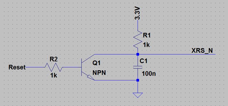
I am looking for a reset circuit for a C2803x processor, where the reset can be set by a GPIO Pin of a FPGA. Since I could not find an example, I tried to make my own one.

Do you think that this can work?

-Thomas


  • Thomas,

    I think it would be simpler to configure your FPGA in an Open-Drain configuration. 

    1) FGPA GPIO Drive-Low when asserting reset
    2) FPGA GPIO tri-state when releasing reset. 

    The external pull-up R1 will pull up the XRS_N pin.  I would use a weaker R1 though, something between 2.2k and 10k ohm.

    You can also refer to the article here for some sample circuits to piece things together in case you need a WDFlag:

    http://processors.wiki.ti.com/index.php/WDFlag_on_Piccolo

    Best regards,

    Jason

  • Hello Jason,

    thanks for your answer.

    I forgot to mention, that there is a digital isolator between the FPGA and the uC. The digital isolator has four channels and one enable PIN. Since I need the other channels I have to enable the isolator and so I lose the tri-state functionality. I know that it would be possible to use 2 isolators or an isolator with open collector output, but I would like to use our standard isolator.

    -Thomas
  • Thomas,

    Okay, that makes sense.  Your circuit looks reasonable to me for that case.  I haven't worked much with isolators or NPN's like this so not sure if there is any other concern.  Just thinking out loud... On/Off resistance of the NPN should be checked, current through R2, power up conditions.  Are there boundary cases when the isolator isn't enabled?  Should there be a weak pull on the gate of the NPN?  

    Best regards,
    Jason