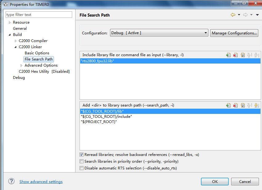
你好,我用的是dsp28335,ccsv6版本,调试的程序是用定时器终端控制流水灯。但是编译程序的时候,出现上面的错误。这是工程的设置以及程序。
#include "DSP2833x_Device.h" // DSP2833x Headerfile Include File
#include "DSP2833x_Examples.h" // DSP2833x Examples Include File
#define LED1 GpioDataRegs.GPADAT.bit.GPIO0
#define LED2 GpioDataRegs.GPADAT.bit.GPIO1
#define LED3 GpioDataRegs.GPADAT.bit.GPIO2
#define LED4 GpioDataRegs.GPADAT.bit.GPIO3
#define LED5 GpioDataRegs.GPADAT.bit.GPIO4
#define LED6 GpioDataRegs.GPADAT.bit.GPIO5
interrupt void ISRTimer0(void);
void configtestled(void);
void main(void)
{
// Step 1. Initialize System Control:
// PLL, WatchDog, enable Peripheral Clocks
// This example function is found in the DSP2833x_SysCtrl.c file.
InitSysCtrl();
// Step 2. Initalize GPIO:
// This example function is found in the DSP2833x_Gpio.c file and
// illustrates how to set the GPIO to it's default state.
// InitGpio(); // Skipped for this example
InitXintf16Gpio(); //zq
// Step 3. Clear all interrupts and initialize PIE vector table:
// Disable CPU interrupts
DINT;
// Initialize the PIE control registers to their default state.
// The default state is all PIE interrupts disabled and flags
// are cleared.
// This function is found in the DSP2833x_PieCtrl.c file.
InitPieCtrl();
// Disable CPU interrupts and clear all CPU interrupt flags:
IER = 0x0000;
IFR = 0x0000;
// PIE 向量表指针指向中断服务程(ISR)完成其初始化.
// 即使在程序里不需要使用中断功能,也要对 PIE 向量表进行初始化.
// 这样做是为了避免PIE引起的错误.
// The shell ISR routines are found in DSP2833x_DefaultIsr.c.
// This function is found in DSP2833x_PieVect.c.
InitPieVectTable();
// Interrupts that are used in this example are re-mapped to
// ISR functions found within this file.
EALLOW; // This is needed to write to EALLOW protected registers
PieVectTable.TINT0 = &ISRTimer0;
//PieVectTable.XINT13 = &cpu_timer1_isr;
//PieVectTable.TINT2 = &cpu_timer2_isr;
EDIS; // This is needed to disable write to EALLOW protected registers
// Step 4. Initialize the Device Peripheral. This function can be
// found in DSP2833x_CpuTimers.c
InitCpuTimers(); // For this example, only initialize the Cpu Timers
// Configure CPU-Timer 0, 1, and 2 to interrupt every second:
// 150MHz CPU Freq, 1 second Period (in uSeconds)
ConfigCpuTimer(&CpuTimer0, 150, 500000);
//ConfigCpuTimer(&CpuTimer1, 150, 1000000);
//ConfigCpuTimer(&CpuTimer2, 150, 1000000);
StartCpuTimer0();
// Enable CPU int1 which is connected to CPU-Timer 0, CPU int13
// which is connected to CPU-Timer 1, and CPU int 14, which is connected
// to CPU-Timer 2:
IER |= M_INT1;
//IER |= M_INT13;
//IER |= M_INT14;
// Enable TINT0 in the PIE: Group 1 interrupt 7
PieCtrlRegs.PIECTRL.bit.ENPIE = 1;
PieCtrlRegs.PIEIER1.bit.INTx7 = 1;
// Enable global Interrupts and higher priority real-time debug events:
EINT; // 总中断 INTM 使能
ERTM; // 使能总实时中断 DBGM
configtestled();
LED1=0;
DELAY_US(10);
LED2=0;
DELAY_US(10);
LED3=0;
DELAY_US(10);
LED4=0;
DELAY_US(10);
LED5=0;
DELAY_US(10);
LED6=0;
DELAY_US(10);
for(; ;)
{
}
}
interrupt void ISRTimer0(void)
{
CpuTimer0.InterruptCount++;
// Acknowledge this interrupt to receive more interrupts from group 1
PieCtrlRegs.PIEACK.all = PIEACK_GROUP1; //0x0001赋给12组中断ACKnowledge寄存器,对其全部清除,不接受其他中断
CpuTimer0Regs.TCR.bit.TIF=1; // 定时到了指定时间,标志位置位,清除标志
CpuTimer0Regs.TCR.bit.TRB=1; // 重载Timer0的定时数据
LED1=~LED1;
LED2=~LED2;
LED3=~LED3;
LED4=~LED4;
LED5=~LED5;
LED6=~LED6;
}
void configtestled(void)
{
EALLOW;
GpioCtrlRegs.GPAMUX1.bit.GPIO0 = 0; // GPIO0 = GPIO0
GpioCtrlRegs.GPADIR.bit.GPIO0 = 1;
GpioCtrlRegs.GPAMUX1.bit.GPIO1 = 0; // GPIO1 = GPIO1
GpioCtrlRegs.GPADIR.bit.GPIO1 = 1;
GpioCtrlRegs.GPAMUX1.bit.GPIO2 = 0; // GPIO2 = GPIO2
GpioCtrlRegs.GPADIR.bit.GPIO2 = 1;
GpioCtrlRegs.GPAMUX1.bit.GPIO3 = 0; // GPIO3 = GPIO3
GpioCtrlRegs.GPADIR.bit.GPIO3 = 1;
GpioCtrlRegs.GPAMUX1.bit.GPIO4 = 0; // GPIO4 = GPIO4
GpioCtrlRegs.GPADIR.bit.GPIO4 = 1;
GpioCtrlRegs.GPAMUX1.bit.GPIO5 = 0; // GPIO5 = GPIO5
GpioCtrlRegs.GPADIR.bit.GPIO5 = 1;
EDIS;
}
//===========================================================================
// No more.
//===========================================================================


