


Hi, I've got a problem with a 2808 SPI interface being used as slave. The problem is that occasionally there are extra pulses on the SOMI line that cause erroneous data to be received by the master. The strange thing is that this situation only occurs SOMETIMES after a power on reset. On one power up the data would be good for an entire session, after another power up the data gets these erroneous pulses and continues to have these pulses during the entire session, but they don't occur in every word. There is no difference in the way the power is cycled in either case.
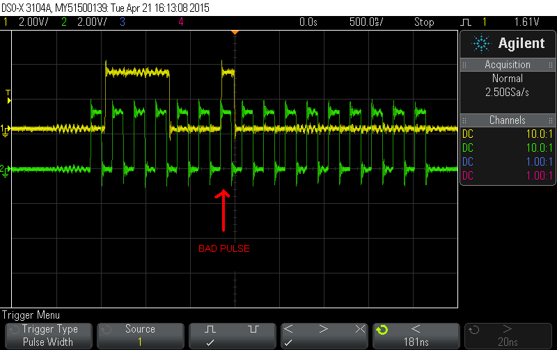
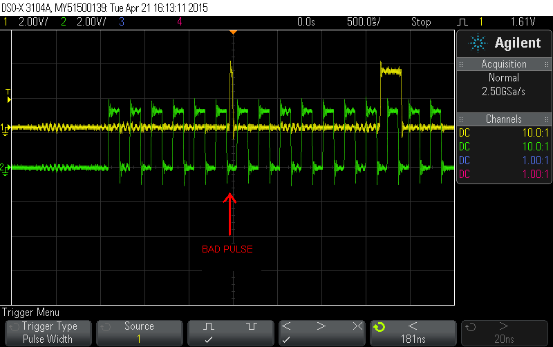
My slave SPI in the 2808 is setup for rising clock edge with 1/2 cycle delay before the rising edge, 16 bit data, Tx FIFO disabled. In the attached plots there are good pulses and bad pulses (labelled) showing the data and corresponding clock edges. I have also tried the SPI GPIO pins configured as sync and async modes with no difference. Also, the changing the master clock speed makes no difference.
It's my understanding that in SPI slave mode the only way data can change is with master clock edges. That doesn't seem to be the case here and the data changes at times other than the falling clock edge.
In the plots below, trace 1 yellow is SOMI (from 2808), trace 2 green is SCLK (from master). These plots are taken very close to the DSP pins.

Here's the SPI init code:
// Initialize SPI FIFO registers
SpiaRegs.SPICCR.bit.SPISWRESET=0; // Reset SPI
SpiaRegs.SPICCR.all=0;
SpiaRegs.SPICCR.bit.CLKPOLARITY=0; // set up for rising edge with delay
SpiaRegs.SPICCR.bit.SPICHAR=15; // 16 bit characters
SpiaRegs.SPICTL.all=0;
SpiaRegs.SPICTL.bit.CLK_PHASE=1; // delayed clock pulse
SpiaRegs.SPICTL.bit.MASTER_SLAVE=0; // Slave
SpiaRegs.SPICTL.bit.TALK=1; // Talk enabled
SpiaRegs.SPICTL.bit.SPIINTENA=1; // Interrupt enabled
SpiaRegs.SPIPRI.all=0x0000; // Free run in emulation mode
SpiaRegs.SPISTS.all=0x0000;
temp = SpiaRegs.SPIRXBUF; //clear any pending ISR
// Enable interrupts for SPIA Rx
PieCtrlRegs.PIEIER6.bit.INTx1=1; //INT6 bit 0 SPIA Rx INT
SpiaRegs.SPICCR.bit.SPISWRESET=1; // Enable SPIA
SpiaRegs.SPITXBUF = 0x0525; //preload state 1
The way the code works is upon receipt of the SPI Rx interrupt, the ISR reads the SPIRXBUF register then loads the next word into the SPITXBUF register. The master clock is 4MHz x 16 bits =4uS per word transfer. There is a 52uS delay in the master between word requests. The 2808 has a 20MHz clock with the SYSCLK running at 100MHz.
One thing to note is that we are NOT using the SPISTE line. There are no GPIO's configured for this function.
Is not controlling SPISPTE a problem?
Could not controlling SPISPTE cause what we're seeing?
Can I just tie SPISPTE low in hardware and enable a GPIO as this function?
Thank you.


