Other Parts Discussed in Thread: TMS320F28335, CONTROLSUITE
Hi,
Target: TMS320F28335 Delfino Microcontroller Emulator: XDS100v2 IDE: Code Composer 5.5
Application Background: In this device we run a compressor controller application that interfaces to a customer board over CAN bus and process commands (i.e., speed up, slow down, etc). The application is all working fine.
I was given the task to add the proper enable and kick the watchdog to provide us with a safe reset in case the application hangs. I have added the code to enable and kick the watchdog at an adequate frequency to avoid a watchdog reset while the application is running properly. I also have code in place so that I can command the application to stop kicking the dog and let it expire. When I do this I set a GPIO to high so that I can monitor this command with the scope. Then ~280msec later (as expected with the 30MHz oscillator / 512 / 64) the watchdog reset the board (my GPIO is reset to 0) all relays and LEDs go through initialization and my application is back to normal.
One of the most important requirements is for us to determine that we were reset by the watchdog so that we can record this anomaly. According to the documentation this should be accomplished by inspecting the state of the WDFLAG. However this flag does not get set as documented in both the Data Manual (SPRS439M) or the System Control and Interrupts (SPRUFB0D) documents. So I need help to determine why is this flag not getting set to 1 on a watchdog reset.
Here are the initialization steps in my watchdog init function:
bool Watchdog_checkAndInitialize()
{
bool boardWasResetByWatchdog = false;
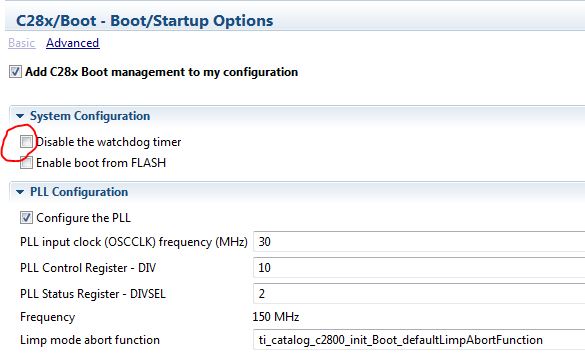
// Configuration for the Watchdog Control Register (WDCR)
// bit 15:8 Reserved (writing to these bits has no effect)
// bit 7 WDFLAG - 0 is ignored in this bit
// bit 6 WDDIS - 0 enables the watchdog module
// bit 5:3 WDCHK - 101b = 5 to avoid an immediate device reset
// bit 2:0 WDPS - 111b = 7 to select 64 as the prescaler for the
// wdclock signal producing a 916Hz clock
//
// Time for watchdog to expire is determined as follows:
// - 30MHz OSCCLK / 512 / 64 = 916Hz clock
// - 256 counts / 916 counts per second = 280msec
//
// Register Initialization Value:
// F E D C B A 9 8 7 6 5 4 3 2 1 0 bit position
// 0 0 0 0 0 0 0 0 0 0 1 0 1 1 1 1 binary setting per bit
// 0 0 2 F hex set value
uint16_t watchdogConfigurationValue = 0x002F;
// WDCR bit 7 WDFLAG - if this bit is 1 the watchdog caused the reset
if ( (SysCtrlRegs.WDCR & 0x0080) != 0 )
{
boardWasResetByWatchdog = true;
watchdogConfigurationValue |= 0x0080; // set WDFLAG clear bit in configuration value
}
// Allow for watchdog to be configured via the System Control and Status Register (SCSR)
// bit 15:3 Reserved - writing to these bits has no effect
// bit 2 WDINTS - read only, state of WDINT signal
// bit 1 WDENINT set to 0 to configure watchdog to do a reset
// bit 0 WDOVERRIDE set to 1 allows to change WDDIS in WDCR
EALLOW; // Below register is "protected", allow access.
SysCtrlRegs.SCSR = 0x0001;
EDIS; // Disable register access
EALLOW; // Below register is "protected", allow access.
SysCtrlRegs.WDCR = watchdogConfigurationValue;
EDIS; // Disable register access
isWatchdogInitialized = true;
//--------------------------------------------------------------------------------------------------
// RR - DEBUG BLOCK START -- TODO REMOVE BLOCK BEFORE COMMIT
if ( boardWasResetByWatchdog ) GpioDataRegs.GPASET.bit.GPIO11 = 1; // this one allows me to see in the scope that WDFLAG was set
GpioDataRegs.GPASET.bit.GPIO5 = 1; // this one allows me to see in the scope that this code executed
// RR - DEBUG BLOCK STOP
//--------------------------------------------------------------------------------------------------
return boardWasResetByWatchdog;
}
I have performed the following measurements:
- From power on (CH1) to XRS (CH2) signal high there are about 240msec

- During the watchdog reset (CH1 monitors my debug GPIO set high upon command to let watchdog expire) the XRS (CH2) signal remains high
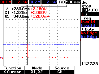
Per TI documentation the XRS signal is supposed to go low for 512 OSCCLK. But this does not happens.
Questions:
- Is the WDRST signal tied to the XRS signal inside the microcontroller or is this something we are supposed to do in our custom board?
- Does my code above looks correct?
- Is there a watchdog setup and WDFLAG check sample code available?
- Why the WDFLAG not getting set to 1?
Thank you.
Rafael