This thread has been locked.

If you have a related question, please click the "Ask a related question" button in the top right corner. The newly created question will be automatically linked to this question.

TMS320F28377D + SMSC LAN9218 How to config EMIF

Other Parts Discussed in Thread: CONTROLSUITE

Hello,

I hope someone can help me.

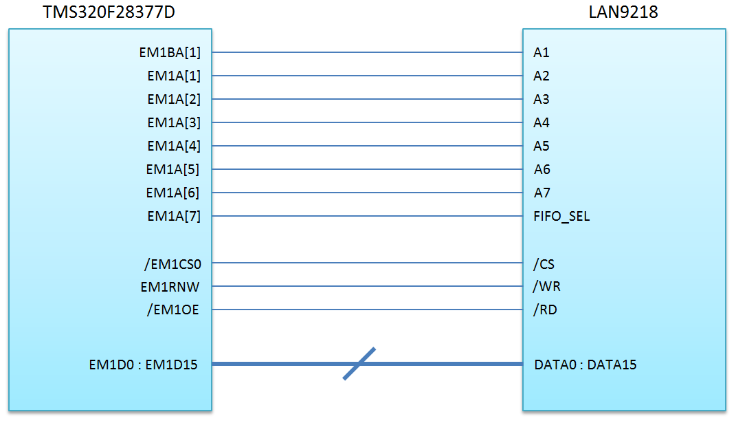
I am trying to config the EMIF. The Ethernet Controller is connected as seen bellow:

I have several question:

1.) Is it possible to use the /EM1CS0 pin although it is not a CS pin used for asynchronous devices?

2.) Someone missed the EM1A[0] address pin. Is it anyway possible to use this layout?

3.) How do I have to config the EMIF ??? Can someone give me a hint?

4.) In the emif1_16bit_asram example from the control suite the ASRAM_CS2_START_ADDR is 0x100000. In the ASYNC_CS2_CR register

all the configurations are made. How can I config the EMIF without using the CS2 pin?

I am looking forward to your answer(s).

With kindly regards.

Werner

  • Hi Werner,

    1.) Is it possible to use the /EM1CS0 pin although it is not a CS pin used for asynchronous devices?

    CS0 is chip select for SDRAM interface and it cannot be used for AYNC Interface unless you want tp program this pin as GPIO and emulate it as CS for ASYNC using software.

    2.) Someone missed the EM1A[0] address pin. Is it anyway possible to use this layout?

    In this not only EM1A[0] is missed but also EM1BA1 is connected to A1 of memory device instead of A0. I don't think this will work.

    3.) How do I have to config the EMIF ??? Can someone give me a hint?

    Please refer the example code in controlSUITE.

    4.) In the emif1_16bit_asram example from the control suite the ASRAM_CS2_START_ADDR is 0x100000. In the ASYNC_CS2_CR register all the configurations are made. How can I config the EMIF without using the CS2 pin?

    If you are emulating the chip select using the GPIO pins instead of CS2, you still need to configure the ASYNC_CS2_CR register (or any other ASYNC configuration register).

    Having said that, I would strongly recommend to have the layout corrected and make proper connection for all the signals.

    Regards,

    Vivek Singh

  • Hello Vivek,

    thank you very much for your answer.

    Because I cannot change the layout I try to emulate the LAN controller.

    I configed all pins to GPIO Pins. Right now I just try to read the ID_REQ (0x50)

    of the LAN controller:

    I do following:

            Uint16 word = 0x0050; //ID_REV
    	Uint32 read;
    
    	GPIO_WritePin(92,0); //EM1BA[1]  --> Address 0 (0=lower 16 bit)
    
    	GPIO_WritePin(39, word & 0x01); //Address 1
    	GPIO_WritePin(40, word & 0x02); //Address 2
    	GPIO_WritePin(41, word & 0x04); //Address 3
    	GPIO_WritePin(44, word & 0x08); //Address 4
    	GPIO_WritePin(45, word & 0x10); //Address 5
    	GPIO_WritePin(46, word & 0x20); //Address 6
    	GPIO_WritePin(47, word & 0x40); //Address 7
    
    	GPIO_WritePin(32, 0); // /CS low active
    	GPIO_WritePin(33, 1); //EM1RNW --> /WR
    	GPIO_WritePin(37, 0); // /EM1OE --> /RD
    
    	read = GPIO_ReadPin(85);				//data0
    	read = read | (GPIO_ReadPin(83)<<1);    //data1
    	read = read | (GPIO_ReadPin(82)<<2);    //data2
    	read = read | (GPIO_ReadPin(81)<<3);    //data3
    	read = read | (GPIO_ReadPin(80)<<4);    //data4
    	read = read | (GPIO_ReadPin(79)<<5);    //data5
    	read = read | (GPIO_ReadPin(78)<<6);    //data6
    	read = read | (GPIO_ReadPin(77)<<7);    //data7
    	read = read | (GPIO_ReadPin(76)<<8);    //data8
    	read = read | (GPIO_ReadPin(75)<<9);    //data9
    	read = read | (GPIO_ReadPin(74)<<10);   //data10
    	read = read | (GPIO_ReadPin(73)<<11);   //data11
    	read = read | (GPIO_ReadPin(72)<<12);   //data12
    	read = read | (GPIO_ReadPin(71)<<13);   //data13
    	read = read | (GPIO_ReadPin(70)<<14);   //data14
    	read = read | (GPIO_ReadPin(69)<<15);   //data15
    
    	asm(" NOP");
    
    	GPIO_WritePin(32, 1); //CS low active
    	GPIO_WritePin(37, 1); // /EM1OE --> /RD
    
    	asm(" NOP");
    
    	GPIO_WritePin(32, 0); //CS low active
            GPIO_WritePin(37, 0); // /EM1OE --> /RD
    
            asm(" NOP");
    
            GPIO_WritePin(32, 1); //CS low active
            GPIO_WritePin(37, 1); // /EM1OE --> /RD
    

    I want to read:

    Unfortunately I cannot read anything. All data pins stay low :(

    What am I doing wrong?

    Greetings,

    Werner

  • Hi Werner,

    One observation -

    EM1A7 is actually connected to FIFO_SEL (not to MSB of address) and A1-A7 of remote device are connected to EM1BA1 - EM1A6.

    In your code you are driving the address pins like -

    GPIO_WritePin(92,0); //EM1BA[1]  --> Address 0 (0=lower 16 bit)
    GPIO_WritePin(39, word & 0x01); //Address 1
    GPIO_WritePin(40, word & 0x02); //Address 2
    GPIO_WritePin(41, word & 0x04); //Address 3
    GPIO_WritePin(44, word & 0x08); //Address 4
    GPIO_WritePin(45, word & 0x10); //Address 5
    GPIO_WritePin(46, word & 0x20); //Address 6

    If 0x50 need to be driven on remote device address line A1-A7 then this may not be driving the correct value instead code should be like this.

    GPIO_WritePin(92,0); //EM1BA[1]  --> Address 0 (0=lower 16 bit)
    GPIO_WritePin(39, word & 0x02); //Address 1
    GPIO_WritePin(40, word & 0x04); //Address 2
    GPIO_WritePin(41, word & 0x08); //Address 3
    GPIO_WritePin(44, word & 0x10); //Address 4
    GPIO_WritePin(45, word & 0x20); //Address 5
    GPIO_WritePin(46, word & 0x40); //Address 6

    Best thing would be to capture the waveform using logic analyzer and check the value on address bus and timing of control signals.

    Regards,

    ViveK Singh

  • I know this is a old post. but we have a prototype board project that we basically finished using a serial interface.  We eventually figured out we need more acquisition speed then the top serial speed and have decided to go with Ethernet. Our prototype had a add-on plug connector for adding more memory using EMiF, but found we didnt need it, so we had our board designer company look at it and they said they could build a simple addon board for ethernet 10/100 using the LAN9218 chip connected to our EMFI (F28377D chip). Ive only been using the C2000 series board for about 5 months and have not had to many issues getting what we needed programmed figured out, but mostly because TI.com has great sample programs for every function. This new add-on isnt standard and your example for memory expansion (although may lead to a finished program eventually), it seems like this thread is doing EXACTLY what our project is doing, and I WOULD LOVE access to any code you may have to offer that would help me complete this add-on code in a timely and easy to understand manner.  

    Thank you for any assistance you may be able to offer,

    Chuck

  • I know this is a old post. but we have a prototype board project that we basically finished using a serial interface. We eventually figured out we need more acquisition speed then the top serial speed and have decided to go with Ethernet. Our prototype had a add-on plug connector for adding more memory using EMiF, but found we didnt need it, so we had our board designer company look at it and they said they could build a simple addon board for ethernet 10/100 using the LAN9218 chip connected to our EMFI (F28377D chip). Ive only been using the C2000 series board for about 5 months and have not had to many issues getting what we needed programmed figured out, but mostly because TI.com has great sample programs for every function. This new add-on isnt standard and your example for memory expansion (although may lead to a finished program eventually), it seems like this thread is doing EXACTLY what our project is doing, and I WOULD LOVE access to any code you may have to offer that would help me complete this add-on code in a timely and easy to understand manner.

    Thank you for any assistance you may be able to offer,

    Chuck
  • Hi Walker,

    We may not exactly have what you are looking for but I am opening this thread and assigning one my colleague to provide any additional on this.

    Regards,

    Vivek Singh

  • That would be great, we're(as most projects) are under a tight time crunch, and this was dumped in my lap.
    What ever info you have will help greatly. Since the emif can be used with multiple type devices, I was hoping there was sample code out there for other type of uses to help get me started In figuring this thing out.

    I have 1week to let them know if the device they built works or not, I don't have to finish the project, just prove we are able to communicate using udp-protocol from a computer using labview thru this network adapter addon to our main project using the f28377d chip using our emif port..

    Thanks

    Chuck
  • just curious, when will someone be replying?

    chuck

  • Still no replys in the past week...
    heres a little more info: We have a LAN-9218 as described in the original part of this thread, it IS wired up correctly based on the schematics. We used the 16bit/32bit AsyncRam EMIF example and have tried everything to atleast read the ID# off the chip. at location 0x50+base (base is shown in the example as 0x100000).

    in the end I simply just commented out the write code on the read/write funciton of the example code, leaving the read part. changed the memory location to 0x100050. and I get a '0' under CCS value expressions section (yes i have refresh turned on).

    we had a professional company design and biuld this add-on. our only goal is to read/write UDP packets directly from a dedicated network card on pc (running labview) to a Delfino F28377D Controller card (custom designed around the chip. We have successfully got our program working on both Labview and the countroller card, but found we need faster aquisition speed then a serial interface would allow. So we are now trying to go ETHERNET. We had the company who built our controller device create a Ethernet add-on card to connect to our memory expansion slot we didnt actually need. The chip is designed to connect with EMIF- Async.

    Our dept is ready for us to give them the green light to create a final version single board device and Using the info from the Delfino manual and the 126 page manual LAN-9218 Ethernet chip. And can not get anything talking. could be a board design flaw, could be operator error, also could be examples that dont properly work (had many of those over the last few months working on what we do have done).

    I could really use some help here. You see what im trying to accomplish above. You also see what ive tried.

    Thank you for any help you can offer.

    Chuck

  • Chuck,

    I'm not the intended colleague, but I'll see if I can help out.

    Do you have a current schematic that you can share? The original schematic in the thread had errors so it would be good for us to review what you are working with now.

    -Tommy
  • Chuck,
    As Tommy suggested, please update the schematics to get them looked at.
    Your approach seems proper. If the address and data lines from 2837x EMIF to the LAN9218 Async 16 bit host bus interface are wired correctly and if you are putting the right address on the bus you should see the value read properly.

    Is there any sample SW from the LAN9218 to implement a 16/32 bit Host bus interface for any other micro controller (like PIC or other)? There could be a protocol that you might have to follow. I haven't read the data sheet completely to understand this but please check if it is direct addressing or if you have to go through a mailbox type of registers where you put address and read data through mailbox registers.

    second, the addressing, from the MCU. Do you need any right shifts to reach the proper address on the LAN9218? Depending on how the address pins from MCU are being mapped to the LAN9218 you might have to verify this.

    Also please scope out all the address pins and CS from MCU and see if the address pins are able toggle properly. For ex: you put 0x5A5A and 0xA5A5 on the address and see the pins being set properly.

    Hope this helps.

    Best Regards
    Santosh Athuru
  • Thank you for your reply, was getting worried I wasn't ever going to get anywhere on this Ethernet part of this project..

    Attached is the drawing of our connection..

    Thanks,

    Chuck

    Link to pdf :

    .

  • drive.google.com/.../view

    Here's a drawing of our basic schematic.

    Chucn
  • Chuck,

    It looks like you have the same error in the address bus and CS hook-up as the original post.

    Also, it looks like you have \WE hooked up to \RD through an inverter. You may want to double-check the LAN9218 signal behavior. Some asynchronous interfaces use the \RD signal for timing considerations. I don't think that \WE will toggle on a read so you would be safer using the dedicated \OE signal.

    -Tommy
  • The lan 9218 has a1 thru A7.  We assume it's just saving a pin because pin a0 is never high on any of the then address given. The manual has no other info on why there is no a0 pin.  

    As for we/... I assume the builder was going for /we = high then /rd = low and vice-verse ...

    Strange there is no specific literature about the a1~a7 pins not having a a0 pin?

    Manual for the chip is at bottom if that helps.

    Thanks

    Chuck

  • Chuck,

    At a minimum, the CSn and address bus signals should be fixed. You can see the correct address mapping in the TRM under Interfacing to Asynchronous Memory. The F2837x address signals are offset by one position for 16b asynchronous memories. CS0 is also not capable of interfacing with asynchronous memories.

    -Tommy
  • Yep... Wasn't sure about the cs0.. can't rewire it, in the final production we can but the prototype board which is surface mount lan9218 can't be fixed right now. What can we do to reassign Cs0 ? Also we are using 32 bit mode not 16...

    As far as the wiring on address lines, it seem s its a1~a7 on both sides. Even in there examples schematics...


    Chuck
  • Chuck,

    There isn't a way to change the CSn assignment except by physical pin routing or by overriding the behavior manually through GPIO control.

    I only see 16 data bits in the schematic so I assume that it is operating in 16b-word mode.

    You may need to follow up with Microchip to find out how to manage the interface. I am not familiar with this device.

    -Tommy
  • The design at the beginning of this thread is not mine. The link I sent two or three reply back is the design. Itshows all 32data pins being used. Rerouting Cs0 if possible can be done, the test board was biult and purchased. Everything is surface mount, cheaper to recode can for proto board then rebiuld board $$$. But our final version can be corrected... Our company won't pay for the final until we prove this design works. Is Cs0 needs to be cs2 and can't be coded/fixed then I'll talk to the boss and tell him someone screwed up and we need to scrap it and start over, but only if your sure.

    Thanks

    Chuck
  • Chuck,

    Yes, you're right. It's 32b so the address pins should be ok.

    That leaves CSn.

    -Tommy
  • Cool....
    Is there a temporary way to reprogram the Cs issue for now . Once we prove everything works, then we can have a final board ordered with the correction, then mass production of our design. But we must prove it works first first.

    Everything works except getting this Ethernet add On programmed...

    Chuck
  • Hello,
    perhaps I can help you with my settings:

    1.) User_Init_EMIF();

    void User_Init_EMIF(void)
    {
    	EALLOW;
    	ClkCfgRegs.PERCLKDIVSEL.bit.EMIF1CLKDIV = 0x0;
    	EDIS;
    
    	EALLOW;
    	///Grab EMIF1 For CPU1
    	Emif1ConfigRegs.EMIF1MSEL.all = 0x93A5CE71; //magic
    
    	//Disable Access Protection (CPU_FETCH/CPU_WR/DMA_WR)
    	Emif1ConfigRegs.EMIF1ACCPROT0.all = 0x0;
    
    	// Commit the configuration related to protection. Till this bit remains set
    	// content of EMIF1ACCPROT0 register can't be changed.
    	Emif1ConfigRegs.EMIF1COMMIT.all = 0x1;
    
    	// Lock the configuration so that EMIF1COMMIT register can't be changed anymore.
    	Emif1ConfigRegs.EMIF1LOCK.all = 0x1;
    
    	EDIS;
    
    	Emif1Regs.ASYNC_CS2_CR.all =  (EMIF_ASYNC_ASIZE_16   | // 16Bit Memory Interface
    			  	  	  	  	  	   EMIF_ASYNC_TA_1 		 | // Turn Around time of 2 Emif Clock
    			  	  	  	  	  	   EMIF_ASYNC_RHOLD_2 	 | // Read Hold time of 1 Emif Clock        _1
    			  	  	  	  	  	   EMIF_ASYNC_RSTROBE_8  | // Read Strobe time of 4 Emif Clock      _4
    			  	  	  	  	  	   EMIF_ASYNC_RSETUP_2 	 | // Read Setup time of 1 Emif Clock       _1
    			  	  	  	  	  	   EMIF_ASYNC_WHOLD_1 	 | // Write Hold time of 1 Emif Clock
    			  	  	  	  	  	   EMIF_ASYNC_WSTROBE_1  | // Write Strobe time of 1 Emif Clock
    			  	  	  	  	  	   EMIF_ASYNC_WSETUP_1 	 | // Write Setup time of 1 Emif Clock
    			  	  	  	  	  	   EMIF_ASYNC_EW_DISABLE | // Extended Wait Disable.
    			  	  	  	  	  	   EMIF_ASYNC_SS_DISABLE   // Strobe Select Mode Disable.
    			  	  	  	  	  	  );
    }

    2.) Read Functions:

    #define ASRAM_CS2_START_ADDR  0x100000
    
    void Read_EMIF(void)
    {
    	Uint16 word = 0x0064; //ID_REV
    	Uint16 read1;
    	Uint16 read2;
    
    	GPIO_WritePin(92,0); //EM1BA[1]  --> Address 0 (0=lower 16 bit)
    
    	GPIO_WritePin(39, word & 0x04); //Address 1
    	GPIO_WritePin(40, word & 0x08); //Address 2
    	GPIO_WritePin(41, word & 0x10); //Address 3
    	GPIO_WritePin(44, word & 0x20); //Address 4
    	GPIO_WritePin(45, word & 0x40); //Address 5
    	GPIO_WritePin(46, word & 0x80); //Address 6
    	GPIO_WritePin(47, word & 0x80); //Address 7
    
    	GPIO_WritePin(32, 0); // /CS low active  //0
    	GPIO_WritePin(33, 1); //EM1RNW --> /WR
    	GPIO_WritePin(37, 0); // /EM1OE --> /RD  //0
    
    	read1 = GPIO_ReadPin(85);                //data0
    	read1 = read1 | (GPIO_ReadPin(83)<<1);    //data1
    	read1 = read1 | (GPIO_ReadPin(82)<<2);    //data2
    	read1 = read1 | (GPIO_ReadPin(81)<<3);    //data3
    	read1 = read1 | (GPIO_ReadPin(80)<<4);    //data4
    	read1 = read1 | (GPIO_ReadPin(79)<<5);    //data5
    	read1 = read1 | (GPIO_ReadPin(78)<<6);    //data6
    	read1 = read1 | (GPIO_ReadPin(77)<<7);    //data7
    	read1 = read1 | (GPIO_ReadPin(76)<<8);    //data8
    	read1 = read1 | (GPIO_ReadPin(75)<<9);    //data9
    	read1 = read1 | (GPIO_ReadPin(74)<<10);   //data10
    	read1 = read1 | (GPIO_ReadPin(73)<<11);   //data11
    	read1 = read1 | (GPIO_ReadPin(72)<<12);   //data12
    	read1 = read1 | (GPIO_ReadPin(71)<<13);   //data13
    	read1 = read1 | (GPIO_ReadPin(70)<<14);   //data14
    	read1 = read1 | (GPIO_ReadPin(69)<<15);   //data15
    
    	asm(" NOP");
    
    	GPIO_WritePin(32, 1); //CS low active     //1
    	GPIO_WritePin(37, 1); // /EM1OE --> /RD   //1
    
    	GPIO_WritePin(92,1); //EM1BA[1]  --> Address 0 (0=lower 16 bit)
    
    	asm(" NOP");
    
    	GPIO_WritePin(32, 0); //CS low active     //0
        GPIO_WritePin(37, 0); // /EM1OE --> /RD   //0
    
        read2 = GPIO_ReadPin(85);                //data0
        read2 = read2 | (GPIO_ReadPin(83)<<1);    //data1
        read2 = read2 | (GPIO_ReadPin(82)<<2);    //data2
        read2 = read2 | (GPIO_ReadPin(81)<<3);    //data3
        read2 = read2 | (GPIO_ReadPin(80)<<4);    //data4
        read2 = read2 | (GPIO_ReadPin(79)<<5);    //data5
        read2 = read2 | (GPIO_ReadPin(78)<<6);    //data6
        read2 = read2 | (GPIO_ReadPin(77)<<7);    //data7
        read2 = read2 | (GPIO_ReadPin(76)<<8);    //data8
        read2 = read2 | (GPIO_ReadPin(75)<<9);    //data9
        read2 = read2 | (GPIO_ReadPin(74)<<10);   //data10
        read2 = read2 | (GPIO_ReadPin(73)<<11);   //data11
        read2 = read2 | (GPIO_ReadPin(72)<<12);   //data12
        read2 = read2 | (GPIO_ReadPin(71)<<13);   //data13
        read2 = read2 | (GPIO_ReadPin(70)<<14);   //data14
        read2 = read2 | (GPIO_ReadPin(69)<<15);   //data15
    
        asm(" NOP");
    
        GPIO_WritePin(32, 1); //CS low active     //1
        GPIO_WritePin(37, 1); // /EM1OE --> /RD   //1
    
    }
    
    Uint32 Read_EMIF_16bit(Uint16 address)
    {
        //Uint32 ASRAM_CS2_START_ADDR = 0x100000;
    	//Uint16 byte_test_ADR_L =  0x0064;
    	//Uint16 byte_test_ADR_H =  0x0065;
        Uint16 byte_test_ADR_L = address;
        Uint16 byte_test_ADR_H = address + 1;
    	Uint32 read_out = 0;
    
    	unsigned short mem_rdl_l;
    	unsigned short mem_rdl_h;
    
    	unsigned long int  Low;
    	unsigned long int  High;
    	short  *XMEM_pl_l;
    	short  *XMEM_pl_h;
    
    	Uint32 jump_in_l = ASRAM_CS2_START_ADDR | byte_test_ADR_L;
    	Uint32 jump_in_h = ASRAM_CS2_START_ADDR | byte_test_ADR_H;
    
    	//set adress
    	XMEM_pl_l= (short *)jump_in_l; //jump in address
    	XMEM_pl_h= (short *)jump_in_h; //jump in address
    
    	//read
    	mem_rdl_l      = *XMEM_pl_l;
    	mem_rdl_h	   = *XMEM_pl_h;
    
    	Low = mem_rdl_h;
    	High = mem_rdl_l;
    
    	read_out = High;
    	read_out |= Low<<16;
    
    	return read_out;
    }
    
    Uint32 Read_EMIF_32bit(Uint16 address)
    {
    	unsigned long mem_rdl;
    	long *XMEM_pl;
    
    	Uint32 jump_in = ASRAM_CS2_START_ADDR | address;
    	XMEM_pl= (long *)jump_in;
    
    	mem_rdl      = *XMEM_pl;
    
    	return mem_rdl;
    }


    To read out the EMIF I used the Read_EMIF_32bit fuction. I hope I could help you.

  • Wow...

    Thank you...

    I'll give it a test run today and see what I can accomplish. This was based on your original hookup (listed at top of this post, right?) or did you change your design any...
    Most importantly this code fixes the Cs0 to cs2 right... Just asking, not getting greedy..

    Thanks

    Chuck
  • DSP LAN9218
    GPIO_33 -----> /WR (93)
    GPIO_34 -----> CS (94)
    GPIO_37 -----> /RD (92)

    GPIO_92 -----> A1 (18)
    GPIO_39 -----> A2 (17)
    GPIO_40 -----> A3 (16)
    GPIO_41 -----> A4 (15)
    GPIO_44 -----> A5 (14)
    GPIO_45 -----> A6 (13)
    GPIO_46 -----> A7 (12)
    GPIO_47 -----> FIFO_SEL (76)
  • The F28377D Technical manual, EMIF section 25.3.6.1 "Interfacing to Asynchronous Memory" shows address connection for 8-bit and 16-bit Memory (Figure 25-9).

    I need to know address connection for 32-bit Memory.

    The 8-bit uses EM1BA[1:0] connected to A[1:0].  The 16-bit uses EM1BA[1] connected to A[0].

    Does 32-bit use EM1BA at all?  Is it a direct connection?

  • Hi John,

    For 32 bit memory interface the address mapping is one-2-one hence it has not been explicitly mentioned. You need to connect A0 of EMIF to A0 of 32bit memory device.

    Regards,

    Vivek Singh

  • After reviewing the code I have a few questions. The first function, Read_EMIF, uses /CS0 (GPIO 32). I see this as an example on how to use CS0 vs. CS2? The other two functions must use /CS2 as that is what is connected according to Pin diagram below? Also I see that you are using EM1RNW vs. /WE for the write enable, either will work?

    I entered the code as shown in Read_EMIF() and it worked!  Thank you!

    To get the manual code to work you have to set GPIO pins to MUX=0, this releases them from EMIF control.

  • Werner,

    Would you connect with me on TI_support(sent a TI_friend req to you). Im working on a project and I am talking to the Lan9218 using your setup. But still having some small issues. The internet just doesnt seem to have much info on this chip nor its setup. Im so out of time and had to request a extention on this project. Im at my wit-ends....
    Since you have the same setup as mine (f28377D + Lan9218), and it doesnt seem ANYONE else on the internet has the same setup, i could really use your help.

    Im just the 'pe-on' programmer on this task (i had no say in the higher ups picking this combination either). But everyone is relying on me to get UDP support working with labView, which works on/off. Ive basically got Send from Lan9218 to labView working consistantly, but keeping the link is impossible with the read function very buggy. I currently have to monitor if a ARP-network request is sent to me from a PC running labview, and when i see it, i have to reply with a ARP-Reply packet. currently i just send one out every 25 secs, seems to work for now on staying linked... but it too is buggy..
    Ive been trying to program this since April (its now almost August).

    Issues:
    (1)When i read the packet and try to read the data, it works the first 2-3 packets, then it shows im reading ahead which is impossible since i read packet size then tell it to read packet size into an Array using a for-loop.
    (2)My setup code for initial setup of the lanchip seems to be buggy (it takes 45secs to finish setting up, yet i have no wait-states that loop that long, they all have timeouts(of 200ms).
    (3)It never shows im linked when i check the (isLinked)-bit.
    (4)plus a few other small hiccups.

    if needed, i will try to offer you something for your time and trouble, as i want to keep my job.

    I was hoping you may let me look at your Lan9218 code in full possibly? I assume you had yours working fully and was talking to a Computer or another device using UDP protocol..

    Thanks

    Chuck
  • Hello,
    I was on my holidays. I will have a look on these issues and hope that I can help you.