This thread has been locked.

If you have a related question, please click the "Ask a related question" button in the top right corner. The newly created question will be automatically linked to this question.

instaspin foc, abnorml current waveform,application in water pumper.

Other Parts Discussed in Thread: MOTORWARE

I’m testing a BLDC,AC 230V in, 2HP, 8 poles,2850RPM rated,application in water pumper.  hardware referenct HVKIT. use mcu 28027F.

motorware version: motorware_1_01_00_14

ccs  Version: 6.0.1.00040.

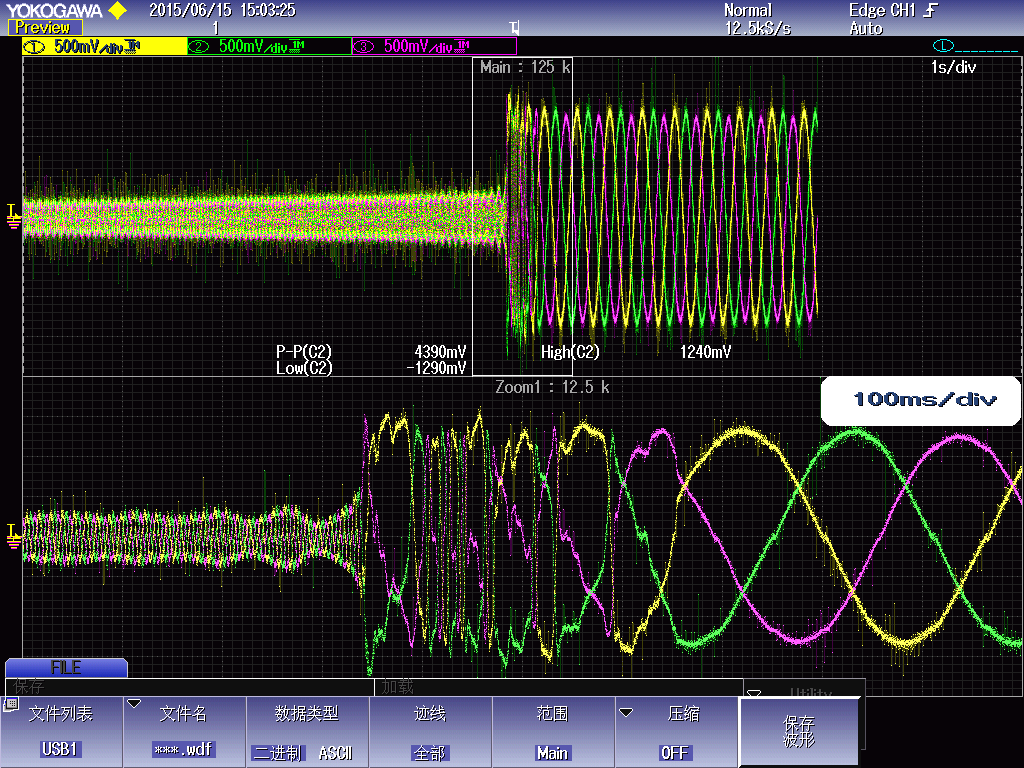
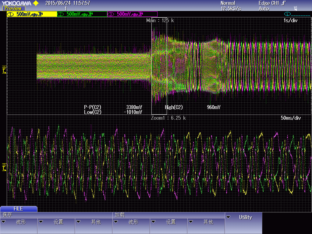
the following figure is an abnormal wave. in the cause of the water pumper acceleration. use lab09.

#define USER_IQ_FULL_SCALE_FREQ_Hz        (500.0)
#define USER_IQ_FULL_SCALE_VOLTAGE_V      (600.0)
#define USER_ADC_FULL_SCALE_VOLTAGE_V       (440.06)
#define USER_IQ_FULL_SCALE_CURRENT_A          (25.0)
#define USER_ADC_FULL_SCALE_CURRENT_A        (46.89)
#define USER_NUM_CURRENT_SENSORS            (3)
#define USER_NUM_VOLTAGE_SENSORS            (3)
#define   I_A_offset    (0.9376856685)
#define   I_B_offset    (0.93725425)
#define   I_C_offset    (0.9360038638)
#define   V_A_offset    (0.2733021379)
#define   V_B_offset    (0.2727869749)
#define   V_C_offset    (0.271528542)
#define USER_SYSTEM_FREQ_MHz             (60.0)
#define USER_PWM_FREQ_kHz                (10.0)
#define USER_NUM_CTRL_TICKS_PER_TRAJ_TICK   (10)
#define USER_MAX_NEGATIVE_ID_REF_CURRENT_A     (-0.5 * USER_MOTOR_MAX_CURRENT)
#define USER_VOLTAGE_FILTER_POLE_Hz  (501.744)
#define USER_MOTOR_MAX_CURRENT          (14.5)

what happend at that moment??? Many tests are like this. The pump is normal, there is no block.

  • Hello Tony,

    Right before you loose control, there are signs that the controller is going unstable. You can see this from the oscillations in the current waveform amplitude. I have a few questions and suggestions:

    1. What does the Iq reference waveform look like right before you lose control? If it is stable, then the problem is most likely with the Iq current PI controller itself. Try lowering the PI gains in the current controllers.

    2. What does your speed signal look like? I suspect it is oscillating in sync with the current waveform amplitude right before you lose control. If so, try lowering the P and I gains of your speed PI controller (especially the P term). In most cases, the current controllers are stable and it is the speed controller that needs to be tuned better.

    3. What happens if you lower the acceleration rate?

    4. What does your bus voltage look like? As the speed increases, you are requiring more power from the bus as a function of speed squared. If your bus caps are too small, you might be seeing some bus ripple that could be contributing to this. Or, you may get into an unstable situation where you are sloshing energy back and forth between your bus caps and the inertia of the motor/load.

    Please let me know what you find.

    Thanks,
    Dave
  • hi dave,

    1. I used to change the kp_spd lower,but no effect. now is about 4.0

    2. I record the screen to show you.

    start up with on load about 3 n.m.

    I can see that the speedTraj_Krpm is not equal Speed_Krpm at that moment.

    and the waveform like this:

    thanks.

    best regards.

  • right at 2300 RPM your flux value rises from 0.6 to 0.75

    what is your Vdc-bus?
    show this variable in the expressions window when you are recording
  • Hi Tony,

    Thanks for collecting this data.  Yeah, I can see that right around 2300 RPM, the speed drops like a rock and the current waveforms look pretty ugly.

    What happens if you lower the speed gain to something extremely low, like 0.5 or 1?  Does it make any difference?

    Also, I would very much like to see plots of Id_ref, Id, Iq_ref, Iq, Vd and Vq using the CCS plot feature if possible.  I suspect your current feedback reading may be contaminated, and I'm hoping I can see that on these plots.

    What is wierd about this is that once you lose control, the system seems to settle down to a stable but lower speed operating mode.  Usually when control is lost, it doesn't find another stable operating mode like this.  Is the motor spinning when this happens?  Does it feel like it is being controlled, or is it like the controller is locked up?

    Also, I see that Iq is zero.  I suspect you just don't have real-time updating set for this variable, but I just wanted to mention it. 

    Regards,

    Dave


  • hi dave,

    1. there is no sudden change on dcbus during acceleration.

    2. i change the kp_spd to 1 or 0.5. the waveform like some change.

    the screen recording:

    change kp_spd to 0.5:

  • the cap of bus is 680UF/450V*2
    dc voltage is about 320V.
    thanks!
  • Is your DC bus stable at 320V the entire time?

    gMotorVars.VdcBus_kV

  • sorry for late.

    yes, gMotorVars.VdcBus_kV is okay in the entire time.

    now my pcb can be run ok after i change the value of LS_Q and LS_D.

    I don't know why the original value testing with LAB02B e can't be run.

  • what were the original Ls values?
    what values did you change them too?

    if you use proj_lab02 to run motor ID what values do you get?