Because of the Thanksgiving holiday in the U.S., TI E2E™ design support forum responses may be delayed from November 25 through December 2. Thank you for your patience.

This thread has been locked.

If you have a related question, please click the "Ask a related question" button in the top right corner. The newly created question will be automatically linked to this question.

Phase current problem at motor high speed

Other Parts Discussed in Thread: DRV8301

23271.user.h

Hello guys

I am using InstaSpin for E-mobility application; this soluction is running on C++ code, keeping the InstaSpin libraries in C code. The user.h file is attached. The solution is working ok, but when the motor speed is close to the motor rated speed the motor phase current looks weird. Using a load (current ripple = 1A), I saved the following pics:

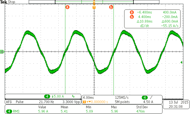
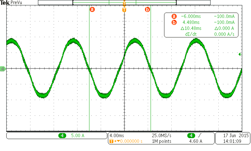
As you can see in figures below, the motor phase current looks ok under Fe= 95.41Hz (10.48ms)

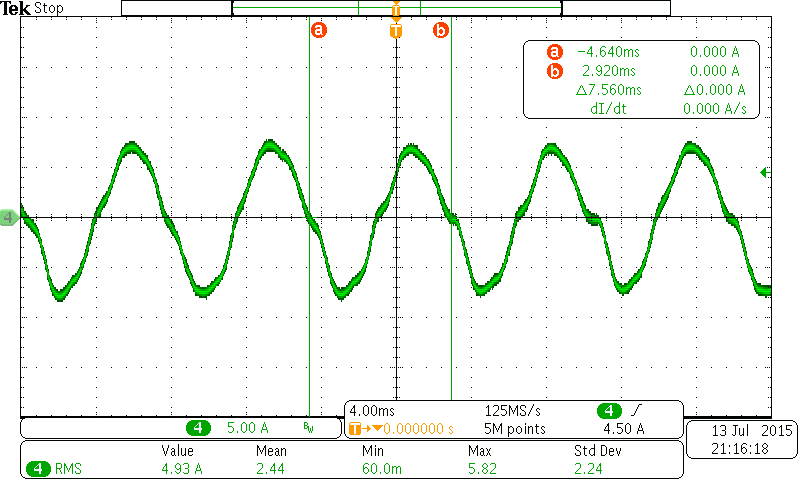
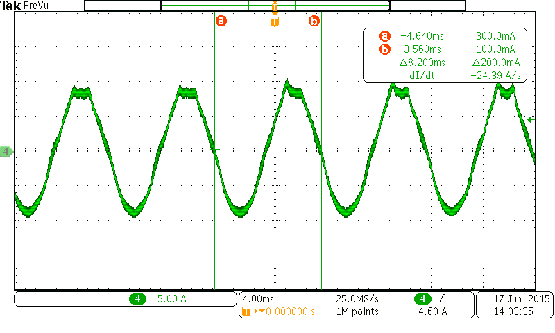
When the motor speed is arround Fe= 121.95Hz (8.2ms), some peaks in the top phase current start to appear (the HW phase current OpAms are in negative scheme):

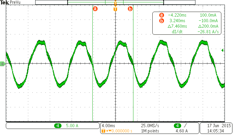
When the motor reach an equilibrium state, the motor phase current looks this:

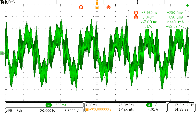
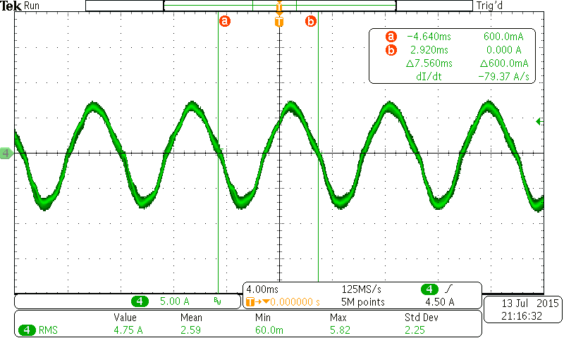
Without any load, the motor reach the maximum speed Fe= 142.45Hz (7.02ms) and phase current looks like this:

I think that back-EMF signal is causing the problem. I already tried to modify the scale factor in the user.h file (SW) and change the voltage sensors calculation (HW) in order to obtain more headroom in the voltage measurement but the result its the same.

1.- What do you recommend to solve the problem?

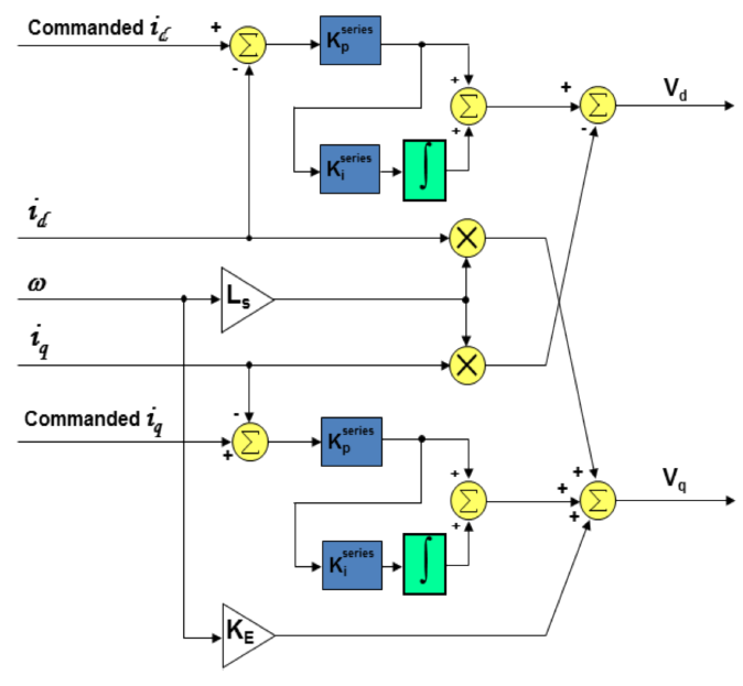
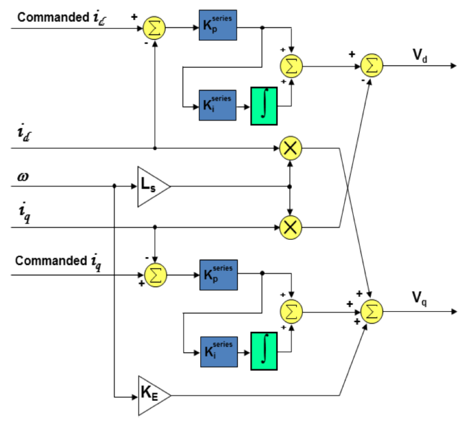
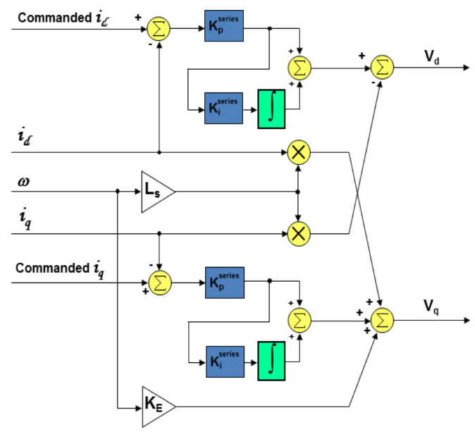
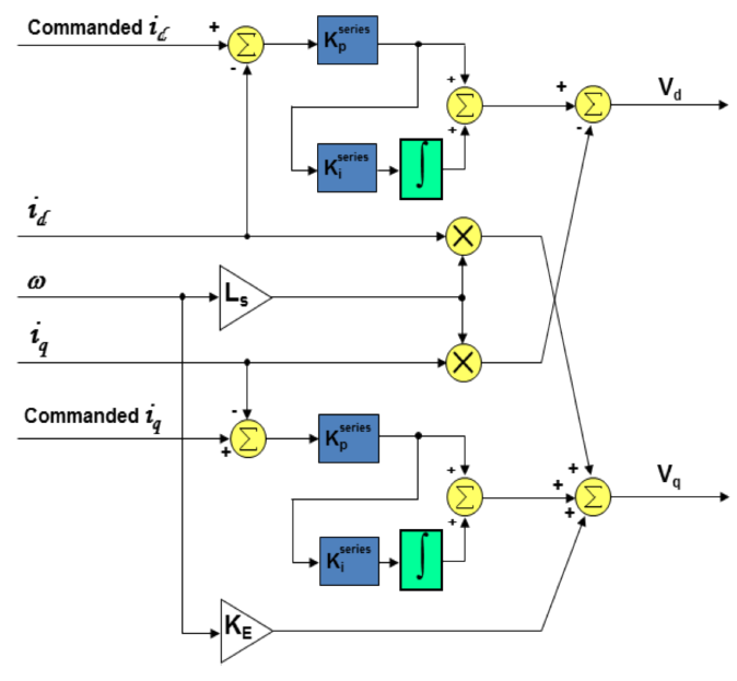
2.- I was reading the InstaSpin documentation (spruhj1f/Figure 11-19) and found this compensation. Is InstaSpin code implementing it?

3.- In case of a negative answer. Do you think that implementing these compensations, could solve the problem?

  • Hello Julio,To answer your questions:
    1. Something is obviously saturating. If you look at the filtered phase-voltage waveforms (at the ADC pins), what do they look like? Could they be saturating which is inhibiting the acquisition of good current readings from your shunt? Also, I would be interested in seeing what Iq_reference and Iq signals look like.
    2. No, InstaSPIN is not presently implementing the compensation scheme shown. This is something that is scheduled for a future release of InstaSPIN.
    3. I don't think it would help. This cross-coupled correction is effective at mitigating transient signals which are naturally cross-coupled in the motor itself. Your waveforms seem to indicate a steady-state clipping which is occurring.
    You may also want to check your PI tuning for the speed controller. But I really think it might be caused by the voltage waveform saturating on the bottom end and starving the current readings.
  • Hi Dave, thanks for your reply

    1. Something is obviously saturating.

    a) If you look at the filtered phase-voltage waveforms (at the ADC pins), what do they look like?

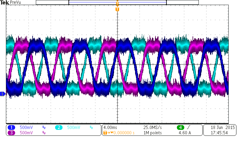
    I made the measurement, the result are shown in Fig 1.1 and Fig 1.2. I think, the negative section of the phase voltage is realy close to the "zero" reference, Do you think this could be the problem?


    Fig 1.1 Three-phase voltages measurement at equilibrium state

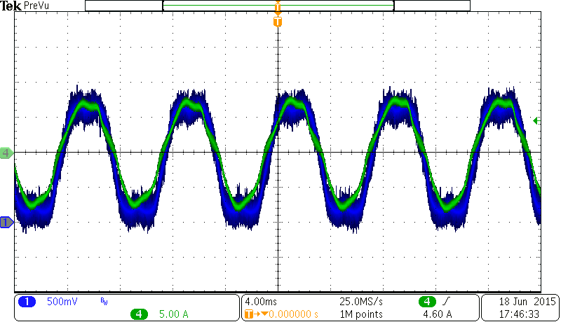
    Once the system reach the equilibrium, the phase voltage looks ok but the phase current looks weird.

    Fig 1.2 Phase voltage and phase current measurement of motor phase U

    b) Could they be saturating which is inhibiting the acquisition of good current readings from your shunt?

    I am not sure if the phase current measurement is perturbated related to it, what kind of HW test do you recommend to verify this?.

    a) Also, I would be interested in seeing what Iq_reference and Iq signals look like.

    Here is the graph of both signals (left: Iq_Ref_A and right: Iq). I am not using the speed controller due to the behaviour of the solution (electric traction). The user governs the current reference, then motor torque and motor speed are increased. As you can see, I set a constant current in order to obtain a semi-constant speed (related to the load applied). The Iq measured (feedback) looks jumping but I think this is caused because the motor torque is bigger that the load torque. Am I wrong?

    2. No, InstaSPIN is not presently implementing the compensation scheme shown. This is something that is scheduled for a future release of InstaSPIN.

    It will be really nice to see this new feature in the future =)

    3. I don't think it would help. This cross-coupled correction is effective at mitigating transient signals which are naturally cross-coupled in the motor itself. Your waveforms seem to indicate a steady-state clipping which is occurring.

    You may also want to check your PI tuning for the speed controller.

    As I mentioned above I am using the current controller scheme. The Kp_Iqd= 0.5688; Ki_Idq= 0.07999 according to the user.h/scalefactor values

    But I really think it might be caused by the voltage waveform saturating on the bottom end and starving the current readings.

    As mentioned above, the only thing is that phase voltages are too much close to the cero reference. What do you recomend to do in this situation?

    Thanks in advance

  • "But I really think it might be caused by the voltage waveform saturating on the bottom end and starving the current readings."
    is the VsRef value (in proj_lab10) saturating to 1.0?

    my initial feeling is the current feedback is getting distorted and FAST is providing inaccurate estimations.
    Is this the DRV8301 EVM or custom HW? If custom, what is the voltage filter pole you have designed?
  • Hi Chris and Dave

    "But I really think it might be caused by the voltage waveform saturating on the bottom end and starving the current readings."
    is the VsRef value (in proj_lab10) saturating to 1.0?

    I think I do not get it, the project 10 is related to "overmodulation" and the ≈150Hz is the rated frequency of this motor.

    Do you suggest to try with the "overmodulation" project?

    my initial feeling is the current feedback is getting distorted and FAST is providing inaccurate estimations.
    Is this the DRV8301 EVM or custom HW?

    It is a custom HW

    If custom, what is the voltage filter pole you have designed?

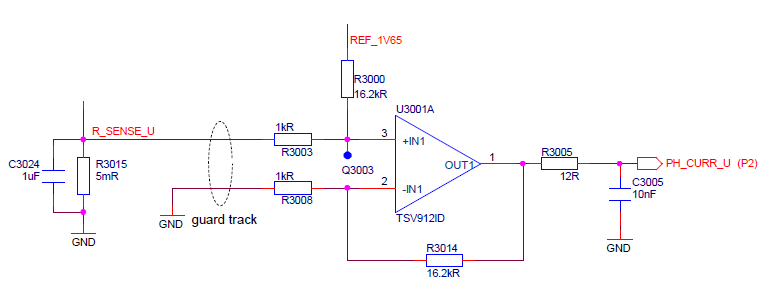
    The following picture shows the original filter designed. The 61.9k Ohms resistor was changed by 82k Ohms in order to increment the measurement headroom; unfortunately, it shown similar results (I made the user.h file update based on the new design values). I made some experimentation with the DRV8301 (project 05a), but the results are similar close to the motor rated speed.

    Do I am doing something wrong?

    What do you recommend for the next step?


  • I think I do not get it, the project 10 is related to "overmodulation"

    - over-modulation changes the maximum Vs that is allowed to be commanded from the torque controller. in this lab Vs reference is calculated/displayed. I was recommending you do this to see where your Vs level is when you start seeing current control issues.

    the filter pole you have designed is around 762 Hz? This is actually higher than you need or want. For your motor 200-300 Hz is fine and would introduce less drift error in your system. I would change this next time you can, but it probably isn't the main issue with your system.

    monitor your Flux value at different speeds and some loads. is it pretty consistent or do you see it moving up or down dramatically with speed?

    is your current sense matching what was done on the DRV8301 EVM or did you change the layout?

    drag and drop your user.h file so we can take a look at the parameters.
  • Hi Chris

    Answering your questions:

    I was recommending you do this to see where your Vs level is when you start seeing current control issues.
    monitor your Flux value at different speeds and some loads. is it pretty consistent or do you see it moving up or down dramatically with speed?

    The figure below is a plot performed with the same load shown the last time (it was a rapid test, I will perform a variable load tomorrow =)). The weird phase currents appears when Vs≈0.9 and motorSpeed≈800RPM which is under the rated speed (868.6RPM). I have a USER_MAX_VS_MAG_PU = 1.0 fixed, as you can see in the user.h file attached.4527.user.h


    the filter pole you have designed is around 762 Hz? This is actually higher than you need or want. For your motor 200-300 Hz is fine and would introduce less drift error in your system. I would change this next time you can, but it probably isn't the main issue with your system.

    Yes it is, I was trying to reuse some components of the BOM list in order to reduce the HW cost. I am going to change it tomorrow.

    is your current sense matching what was done on the DRV8301 EVM or did you change the layout?

    No it is not. As you can see in the figure below, the current feedback has a positive polarity, I made the change in the HAL_updateAdcBias function as suggested by the User Manual (spruhj1f). With this in mind, I had to perform another change in the HAL_readAdcData, specifically in the phase current conversion multiplying by -1.0 in order to change the polarity of the current analyzed due to the negative feedback in the OPAMP configuration designed.

    Do you think that this could be the problem?

    Thanks in advance

  • "The figure below is a plot performed with the same load shown the last time (it was a rapid test, I will perform a variable load tomorrow =)). The weird phase currents appears when Vs≈0.9 and motorSpeed≈800RPM which is under the rated speed (868.6RPM). I have a USER_MAX_VS_MAG_PU = 1.0 fixed, as you can see in the user.h file attached.4527.user.h"

    Vs is saturating to 1.0, meaning you are using all of your Vbus with the 1.0 modulation. You would need to use proj_lab10 to enable over-modulation to increase the available Vs. Start with gMotorVars.Overmodulation = 1.15, that should give you enough headroom.

    Question: in this test, what is your speed reference? 800 RPM? I've found that you often get oscillations when you request a speed very close to the maximum speed at that modulation. It usually helps if you set an even higher speed, that way the speed controller saturates and you just command a stable IqRef to the torque system.

    "is your current sense matching what was done on the DRV8301 EVM or did you change the layout?"
    What you did looks fine. My bigger concern is in the layout of the sense lines and the placement of the OPA. On the DRV8301 EVM the OPA are at the current sense circuit and then the output is transmitted through long traces to the ADC pin. This means there is all sorts of noise and cross talk that is picked up. It is better reduce the length of these traces and put the amplifier closer to the ADC pin.
  • Hi Chris,  thanks for your reply

    Vs is saturating to 1.0, meaning you are using all of your Vbus with the 1.0 modulation. You would need to use proj_lab10 to enable over-modulation to increase the available Vs. Start with gMotorVars.Overmodulation = 1.15, that should give you enough headroom.

    Question: in this test, what is your speed reference? 800 RPM? I've found that you often get oscillations when you request a speed very close to the maximum speed at that modulation. It usually helps if you set an even higher speed, that way the speed controller saturates and you just command a stable IqRef to the torque system.

    My application is an electric bicycle, which assist the user when he is pedaling, the current reference (IqRef) is commanded via a pedal speed sensor (and a look-up table) to increase or decrease the Iq current between 0-12A. Thus, the Speed controller is not used.

    In the current control scheme, the motor is always reaching the maximum speed that the VBus and the load applied can offer. Is it means that even setting gMotorVars.Overmodulation = 1.15, the motor will keep the maximum speed (a new maximum speed) which will cause the same problem?

    Do I have to limit the the maximum speed? How do you recommend to do it?

    "is your current sense matching what was done on the DRV8301 EVM or did you change the layout?"

    What you did looks fine. My bigger concern is in the layout of the sense lines and the placement of the OPA. On the DRV8301 EVM the OPA are at the current sense circuit and then the output is transmitted through long traces to the ADC pin. This means there is all sorts of noise and cross talk that is picked up. It is better reduce the length of these traces and put the amplifier closer to the ADC pin.

    On my board, the OPAMPs to sense the phase currents are placed in the EndStage such as the DRV8301 EVM. However, the traces used to transmit the OPAMP output is not too long such as the DRV8301 EVM (1/5 times shorter). Do you think that this is ok?

  • "to increase or decrease the Iq current between 0-12A. Thus, the Speed controller is not used."
    ok, understand, this is a typical use case.

    "In the current control scheme, the motor is always reaching the maximum speed that the VBus and the load applied can offer. Is it means that even setting gMotorVars.Overmodulation = 1.15, the motor will keep the maximum speed (a new maximum speed) which will cause the same problem?"

    the motor should not hit the maximum speed if there is a load and IqRef is under the rated current. In the test above it does not surprise me that your Vs has saturated and your Velocity has saturated. This is expected with no load and enough IqRef.

    increasing the modulation allows you to apply more effective voltage which would let you reach higher speeds. that decision is up to you.

    your issue is one of current control stability at higher speeds (looks like at about a Vs of ~0.8) the currents begin to distort.

    From a control standpoint, the only thing that could be a problem with FAST is if the inductance is mis-identified. You can lower the Ls values you are using by say 30% and see if there is any change. I doubt this is the issue, but it's easy to check.

    Other than that the culprit would have to be in the current feedback that you are taking from the system. Samples are corrupted and you aren't getting good data into the control system. The DRV8301 EVM is affected by this as mentioned. With your shorter traces it should help, but I'm sure you are still picking up cross talk and noise.
  • Hi Chris, thanks for your reply

    From a control standpoint, the only thing that could be a problem with FAST is if the inductance is mis-identified. You can lower the Ls values you are using by say 30% and see if there is any change. I doubt this is the issue, but it's easy to check.

    I made the test for +-30% but, I have to say that Ls value is quite good.

    the motor should not hit the maximum speed if there is a load and IqRef is under the rated current. In the test above it does not surprise me that your Vs has saturated and your Velocity has saturated. This is expected with no load and enough IqRef.

    You are right, but on the application, I am expecting that applying rated current (12A) the motor can reach the maximum speed at different loads (different user weights or different slope of the rode). My main concern is if this weird phase currents could compromise the motor life. What do you think?

    your issue is one of current control stability at higher speeds (looks like at about a Vs of ~0.8) the currents begin to distort.

    In this application the it is not necessary to run the motor at Vs > 1. I changed the Vs value (Vs < 1) and the results are the same for each saturation (maximum speed related to Vs). Is this means that there is not solution yet for this issue?

    In some reply above, Dave mentioned that the Vd and Vq compensation is not implemented yet in InstaSpin. Do you think that implementing these compensations, could solve the problem?

  • Hi Chris, thanks for your reply

    From a control standpoint, the only thing that could be a problem with FAST is if the inductance is mis-identified. You can lower the Ls values you are using by say 30% and see if there is any change. I doubt this is the issue, but it's easy to check.

    I made the test for +-30% but, I have to say that Ls value is quite good.

    the motor should not hit the maximum speed if there is a load and IqRef is under the rated current. In the test above it does not surprise me that your Vs has saturated and your Velocity has saturated. This is expected with no load and enough IqRef.

    You are right, but on the application, I am expecting that applying rated current (12A) the motor can reach the maximum speed at different loads (different user weights or different slope of the rode). My main concern is if this weird phase currents could compromise the motor life. What do you think?

    your issue is one of current control stability at higher speeds (looks like at about a Vs of ~0.8) the currents begin to distort.

    In this application the it is not necessary to run the motor at Vs > 1. I changed the Vs value (Vs < 1) and the results are the same for each saturation (maximum speed related to Vs). Is this means that there is not solution yet for this issue?

    In some reply above, Dave mentioned that the Vd and Vq compensation is not implemented yet in InstaSpin. Do you think that implementing these compensations, could solve the problem?

  • "You are right, but on the application, I am expecting that applying rated current (12A) the motor can reach the maximum speed at different loads (different user weights or different slope of the rode). My main concern is if this weird phase currents could compromise the motor life. What do you think?"

    while true, I don't understand this logic. You are going to apply maximum torque command all the time? you should be applying a torque command in relation to the pedal sensor.

    "In some reply above, Dave mentioned that the Vd and Vq compensation is not implemented yet in InstaSpin. Do you think that implementing these compensations, could solve the problem?"
    no, I don't think this is the issue at all. we have MANY e-bike/scooter applications in production that are not seeing this issue. I still feel it is related to the sense measurements.
  • "You are right, but on the application, I am expecting that applying rated current (12A) the motor can reach the maximum speed at different loads (different user weights or different slope of the rode). My main concern is if this weird phase currents could compromise the motor life. What do you think?"

    while true, I don't understand this logic. You are going to apply maximum torque command all the time? you should be applying a torque command in relation to the pedal sensor.

    By design, motor assistance is removed at 25 km/h, but the motor is still spinning at the minimum current (1A) in order to obtain the bicycle speed based on motor speed(>25km/h). In this scenario, Vs is saturated and I am concern about it.

    "In some reply above, Dave mentioned that the Vd and Vq compensation is not implemented yet in InstaSpin. Do you think that implementing these compensations, could solve the problem?"
    no, I don't think this is the issue at all. we have MANY e-bike/scooter applications in production that are not seeing this issue. I still feel it is related to the sense measurements.

    I have been trying to track the problem in HW but I think this is not the problem.

    There is one thing that its not clear to me. In the Kp calculation the

    Kp= Ls * 2pi * Bandwidth * (USER_IQ_FULL_SCALE_CURRENT_A / USER_IQ_FUL_SCALE_VOLTAGE)

    Bandwidth= ctrl_period_sec/Factor;

    if Motor_Max_Speed_Hz= 150 and ctrl_period_sec

    Bandwidth= 150 --> Factor= 1/(ctrl_period_sec*Bandwidth) = 10000/150 = 66.66Hz

    Unfortunately, using this factor the phase current is not exactly sinusoidal, so I decreased the factor until reach Bandwidth= 2kHz. The system still stable without weir noise. Do you think that something is wrong?

  • for the current controllers:

    from USER_calcPIgains
    Kp_Iq = _IQ((0.25*Ls_q*fullScaleCurrent)/(ctrlPeriod_sec*fullScaleVoltage));

    the default current control gains will work very well, you should not change them for your application.


    or are you talking about the speed controller?
    personally, I just use trial and error on the speed controller. I don't find the calculations in lab05b to work - or I never have good information on the inertia of the motor to make it work.
  • Hello Julio,


    The bandwidth we are talking about in the Kp calculation is the bandwidth of the current controller, which you want to be MUCH higher than the bandwidth of the speed controller, or of the maximum operating speed of the motor for that matter.  For guidelines on how to calculate Kp for the current controllers, please read my blog series on "Teaching Your PI Controller to Behave".  Specifically, part 6 talks about how to set Kp for the current controller:


    http://e2e.ti.com/blogs_/b/motordrivecontrol/archive/2013/04/04/teaching-your-pi-controller-to-behave-part-vi


    In most cases, you can just leave the PI values for the current controllers set to their autotuned default values, like Chris said.


    Regards,


    Dave


  • Hi Chris and Dave

    Sorry for the delay, the last week I was busy in other project. The Kp gain mentioned is for the Idq current controller. I am not using the speed controller due to the traction application (E-Bike).

    I agree with you guys, the default bandwidth (10000Hz/20 = 500Hz) should to be enough for my motor max frequency (150Hz); unfortunately is not. Using the default bandwidth the result is like in figure

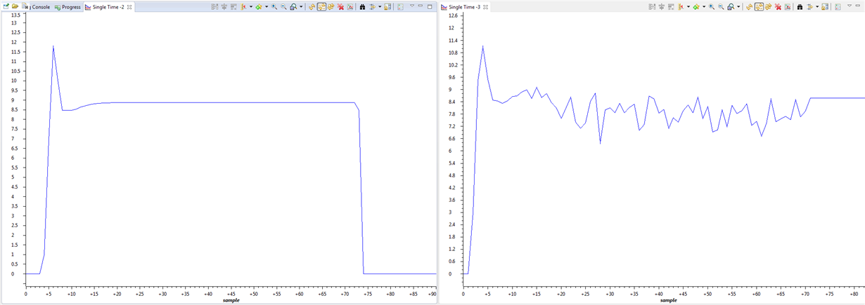
    Fig 1. Phase current U of my own board at default bandwidth

    Using Lab05a I made the same test in the EVM8301 and it displays the following plots.

    Fig 2. Fig 1. Phase current U of EVM board at default bandwidth

    Fig 3. Fig 1. Phase current U of EVM board at 4 times the default bandwidth

    I was always solving this issue using the increment of Kp gain in the Idq controllers. I was thinking that it is ok just because the EVM was presenting the similar current shapes. Do you think that something is wrong with the motor parameters?

    Other thing that is different in my application is a 28 deadband. I set it in reference to the Mosfet parameters

    I am using CCS  Version: 6.1.0.00104 with Compiler: TI v6.4.4. Just in case you need this information.

  • I notice how these EVM pictures look much better than your own HW...that points to a HW difference, does it not? And the DRV8301 EVM is actually not all that good, showing pretty noisy currents over 50% duty cycle.

    both images look "normal" to me based on other e-Bike motors we've seen. they are constructed in a way that lead themselves to this sort of current waveform typically. You can try spinning the motor with an external mechanical source and look at the current generated on the phases...I would bet it looks nearly identical and not completely sinusoidal, if that is what you were looking for.

    I do think your DB is having a bit of effect at the zero crossing points, but that is a limit from your HW that you must just live with.
  • I notice how these EVM pictures look much better than your own HW...that points to a HW difference, does it not? And the DRV8301 EVM is actually not all that good, showing pretty noisy currents over 50% duty cycle.

    Yes, the EVM pictures look better that my own HW. 

    both images look "normal" to me based on other e-Bike motors we've seen. 

    When you say both images, do you mean my HW and EVM or just the EVM pictures? I am a beat worried for the system performance, I do not want to damage the motor or the battery in the final product.

    Do you still thinking that default bandwidth is enough? When the bandwidth is increased, a sinusoidal phase current is generated then, battery energy is used more efficient. Leaving the default bandwidth the battery energy could be wasted. 

    they are constructed in a way that lead themselves to this sort of current waveform typically. You can try spinning the motor with an external mechanical source and look at the current generated on the phases...I would bet it looks nearly identical and not completely sinusoidal, if that is what you were looking for.

    This is the back-EMF of my motor, as you can see it is sinusoidal. This motor has a Gear Reduction Ratio of 1:4.42; picture above was taken with the mechanical reduction ratio until reach 150Hz of phase-phase voltage. Do you think the mechanical reduction is making something in motor mode?

    I do think your DB is having a bit of effect at the zero crossing points, but that is a limit from your HW that you must just live with.

    Yes, I agree.

  • Julio Noel Hermandez said:
    Yes, the EVM pictures look better that my own HW.

    I would focus on this issue.

    Julio Noel Hermandez said:
    When you say both images, do you mean my HW and EVM or just the EVM pictures?

    The EVM pictures.  Well, your motor is more sinusoidal than I expected, so I would chalk up the differences primarily to non ideal current sampling (even on our EVM, which has known issues).  What PWM rate are you using?  I'd suggest using 15 KHz maximum for this motor...not sure if you are still using 45 KHz default.

    I think the increased bandwidth is helping...it is compensating a bit for the non ideal current sampling.

  • Ok, I will focus in the HW differences.

    The EVM pictures.  Well, your motor is more sinusoidal than I expected, so I would chalk up the differences primarily to non ideal current sampling (even on our EVM, which has known issues).  What PWM rate are you using?  I'd suggest using 15 KHz maximum for this motor...not sure if you are still using 45 KHz default.

    In my HW, PWM freq is 20kHz using an ISR of 10kHz (with these values the current ripple is 850mA)

    In the EVM, PWM freq is 45kHz using an ISR of 15kHz (default, just for reduce the current ripple