This thread has been locked.

If you have a related question, please click the "Ask a related question" button in the top right corner. The newly created question will be automatically linked to this question.

double pulse Generation using TMS320F28035 OR F2808

Hello,

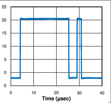
I have requirement to generate two pulses of different Widths from  the Same EPWM module with a small frequency.

For example:

First Pulse Width of 25us   ~>     a delay of 5us   ~>    Second pulse width of 5us     ~>      (Repeat this sequence with a Frequency of 5Hz )

Both pulses have to be from the same EPWM module. Is this possible to generate using DSP ?  

I have attached the expected waveform. Please let me know of any material that I must read to implement this. 

Thank you. 

Regards,

Harsh

  • Harsh.

    This may be possible but you've to have software controlling the PWM outputs.
    One way i can think of -
    Configure PWM to operate at a certain freq. (say 5us) - then software has to take interrupts at 5us rate and keep track of the required output and configure/change the settings accordingly.
    So - for first 5 cycles you can force PWM High, then Low, then Hi, then Low and repeat the sequence as needed in s/w.
    In short - there is no hardware mode which will directly generate the above waveform from PWM but can be achieved using s/w controlling PWM generation.

    -Bharathi.

  • Hello Sir,
    Thank you for clearing up that there isn't any hardware mode to implement this.
    I understand your logic. I will try to implement this.
    Thank you very much for the help.

    Regards,
    Harsh
  • Hi Harsh,

    As you've found there isn't a direct way to do this in hardware.

    You want 4 edges per period.
    Asymmetric PWM can generate up to 3 edges per period.
    Symmetric PWM can generate up to 6 edges per period (but there must be some amount of symmetry in order to really utilize all 6).

    ===

    Besides what Bharathi has mentioned, I believe there is another option.  However, it is a bit tricky and may not be applicable in all situations. I also have not tried to do this specifically before.

    I think you can create your PWM waveform by using two PWM modules.
    1) One PWM is configured to be high until about 31us (according to your figure) then go low based on a CMPA event.  You'd configure it to go high shortly thereafter based on CMPB.
    2) The above PWM would feed into a trip zone input
    3) A second PWM would generate the first 3 edges you need and then rely on a CBC trip zone event to create the 4th.

    For some situations this solution may be adequate.  Obviously you'll need to be careful if the control loop constantly needs to be editing the timing of edges.


    Thank you,
    Brett

  • Can you please share the logic here with code?
    Thank you


    Regards
    Saleem
  • Hello Saleem,

    This thread has been inactive since 2015 so you may not receive a response. For best chances of support, please create a new post. If there is pertinent information in this thread, you can add a link back to this thread in your new post.

    Best Regards,
    Adam Dunhoft