This thread has been locked.

If you have a related question, please click the "Ask a related question" button in the top right corner. The newly created question will be automatically linked to this question.

How to control power generation in ACIM

Other Parts Discussed in Thread: MOTORWARE

We are testing a high current ACIM for use as a generator.

This uses custom hardware controlled by a 28069 microcontroller.

It uses an encoder for position calculation and the slip magnetic angle from the SLIP_getMagneticAngle (slipHandle) call for controller input.

The software is based on Motorware 14 InstaSpin  lab 5a

An example of using and ACIM as a generator is referenced in:

https://e2e.ti.com/support/microcontrollers/c2000/f/171/t/337405

This includes the following diagram.
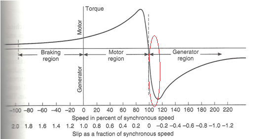
Our current motor to generator transition control is via changes in:

- direct current reference value (Id) and

- direct/quadrature current (Idq)

The questions that we have are:

- What other settings affect power generation and negative torque control?

- What controls can be used to tune this for more efficiency?

- What is the best way to control varying torque over time, both positive and negative?

- In the diagram the braking region takes place with positive torque.  Is there a braking region with negative torque separate from the generator region?

I appreciate your assistance with these questions.

Thanks,

Allan

  • Hi Allan,

    Let me address your questions one at a time:

    - What other settings affect power generation and negative torque control?

    Id and Iq are the main variables.  Both affect the amount of torque, and consequently the amount of power generation.  But they affect torque and power in different ways.  Id sets the rotor flux in the machine, and the time constant for this is typically very long (on the order of several hundred milliseconds, depending on your motor).  So this variable is usually set to reflect long-term operating characteristics of the machine.  Iq sets the quadrature stator current, which is also directly proportional to torque.  But the time constant for the q axis is extremely fast.  The transfer function from Vq to Iq has a time constant which is approximated by adding the stator leakage inductance to the rotor leakage inductance, and then dividing by the stator resistance.  So Iq is the variable you should adjust for quick transient response of your system.

    What controls can be used to tune this for more efficiency?

    Efficiency is best controlled by lowering the flux in the machine.  With older volts-per-hz controllers, the only way you had to do this was to lower the voltage for a given frequency.  But with field-oriented controllers, you can control the flux directly with the Id current setting.  Lowering the flux will manifest itself as increased slip.  In fact, if you look at slip curves for an AC induction motor, you will see that operation for maximum PF is a small slip, operation for maximum torque is a larger slip, and operation for maximum efficiency is an even larger slip.  Many people erroneously assume that maximum efficiency corresponds to maximum torque per amp.  However, while close, this is not entirely true.  There is another operating point which corresponds to the minimum copper losses in the machine for both rotor and stator.  This is the operating point that is exploited in InstaSPIN-FOC's PowerWARP feature which automatically finds this point for a given machine.

    What is the best way to control varying torque over time, both positive and negative?

    Again, both Id and Iq control torque.  But the preferred way is with Iq since it's response time is so much quicker.

    In the diagram the braking region takes place with positive torque.  Is there a braking region with negative torque separate from the generator region?

    If your synchronous speed is negative instead of positive, then the braking region will exist in quadrant 4, where the torque is indeed negative.  But just a note about the braking region:  It is not a very effective or efficient way to stop an AC induction machine due to the extremely high slip that is required.  Perhaps this is not a concern to you.  But if you do need to operate in braking mode, I would consider DC injection.  Technically, since DC injection is at zero Hz, it is still braking since it does not result in regenerated energy.  The energy ends up being dissipated in the motor resistances and the power switches.  But if you are equipped to handle the regenerated energy, the fastest and most efficient way to slow down the motor is to just set your Iq value to the maximum negative limit allowed until the speed slows down to the desired value.  In a field-oriented system, this is automatically accomplished by simply commanding a lower speed, and letting the output clamps of your speed PI controller limit the commanded Iq current to a safe negative value.

    Best Regards,

    Dave


  • Dave,

    Thank you for the information. As we noted at the start of this thread, the ACIM motor is operating in torque mode (modified lab 5A) and the speed loop is disabled.

    Thanks in advance for looking at our follow up questions:

    Regarding the comment:

    "the fastest and most efficient way to slow down the motor is to just set your Iq value to the maximum negative limit allowed until the speed slows down to the desired value."

    - Does this mean that the Id value should not be changed when applying positive or negative torque, and that only the Iq value should be changed? If not, how does the sign/polarity of both Id and Iq affect the torque response?

    - Also, in reference to the diagram in the previous posting above, will setting the Iq value to the maximum negative limit maintain slip in the 0 – 1 range for positive (motoring) torque and slip < 1 for negative (generating) torque? The desired operation is to use generating mode and not the braking mode to apply negative torque.

    - When requesting torque control changes (including changes from positive to negative and negative to positive that are controlled with Iq and/or Id), is there any reason to use speed reference values with a larger absolute value than 0.01?


    Best regards,

    Allan
  • Allan Pelley said:
    - Does this mean that the Id value should not be changed when applying positive or negative torque, and that only the Iq value should be changed? If not, how does the sign/polarity of both Id and Iq affect the torque response?

    typically the Id value is left at the magnetizing current level. if it is set lower your torque capability is diminished, if set higher you would have more torque capability, so I guess you could stop the motor slightly faster, but that isn't usually done

    Allan Pelley said:

    - When requesting torque control changes (including changes from positive to negative and negative to positive that are controlled with Iq and/or Id), is there any reason to use speed reference values with a larger absolute value than 0.01?

    when running in torque mode the absolute value of the speed command is not important, but the sign is critical as it is used in the direction capability inside of FAST.  the Torque function was written to automatically set the sign of the speed controller reference to math the sign of the Iq command.

  • Dave,

    Thank you for answering our questions; I do have a couple of questions to clarify things:

    (1) With respect to the Id value and magnetizing current:

    "typically the Id value is left at the magnetizing current level. if it is set lower your torque capability is diminished, if set higher you would have more torque capability, so I guess you could stop the motor slightly faster, but that isn't usually done."

    - Does this mean that the Id values should always be positive or is this referring to an absolute value and Id could be set to a positive magnetizing current value for positive torque and to a negative magnetiZing current for negative torque (generation mode).

    - What are the consequences of using an Id value greater than the magnetizing current and why is this not usually done?


    (2) Thanks for the clarification on the importance of the sign of the speed reference when torque mode. Does the statement:

    "the Torque function was written to automatically set the sign of the speed controller reference to math the sign of the Iq command."

    mean that it is not necessary for the software to cause the sign of the speed controller to match the sign of the Iq command? And is there any reason that the software should not match the sign in any event?

    Best regards,

    Allan Pelley
  • By the way, the last posting was meant to be addressed to Chris Clearman.

    Allan
  • "- Does this mean that the Id values should always be positive or is this referring to an absolute value and Id could be set to a positive magnetizing current value for positive torque and to a negative magnetiZing current for negative torque (generation mode)."

    Always positive. negative Id would be field weakening in a PM machine. In an induction machine it would mean you aren't inducing any field and the motor would not produce torque to rotate the rotor.

    "- What are the consequences of using an Id value greater than the magnetizing current and why is this not usually done? "
    This is the field boosting region. It is done if you want the motor to produce higher than rated torque for a short period of time. For example this is done in compressor systems that may be initially under a very heavy load. This allows you to properly size the motor to the smallest power possible and not oversize for the very small amount of time you may need large torque at start-up.

    "mean that it is not necessary for the software to cause the sign of the speed controller to match the sign of the Iq command? And is there any reason that the software should not match the sign in any event?"
    The SW we provide already sets a speed command with proper sign. No, the speed reference sign should always match the IqRef sign in torque mode.

    Also, since your project is going to do CW/CCW, make sure that you disable ForceAngle after start-up. It must be disabled when you move through zero speed region between +/- and -/+.