This thread has been locked.

If you have a related question, please click the "Ask a related question" button in the top right corner. The newly created question will be automatically linked to this question.

TZA & TZB versus DCxEVT1 & 2


Hello,

I'm working with the microcontroller TMS320F28062PZPS.

As discovered on the forum topics, there are 2 cases, how the events are treated by EPWM module:

1. Using TZCTL [TZA & TZB]:

In this case the ouput change is applied immediatly upon event detection (for. eg. output is forced low).

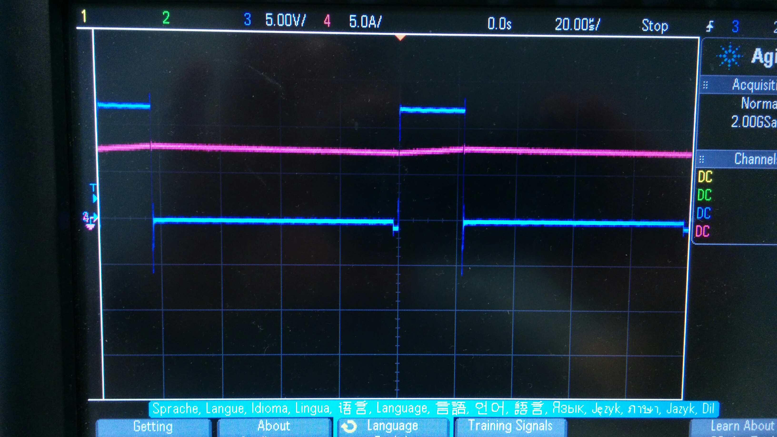
Output then returns back when TBCTR = 0x0000 (for eg. on the start of the next period).

The blue line is PWM, the red line is current. When the current value triggers the event, the pwm goes low and stays low until the next period.

2. Using TZCTL [DCxEVT1 & 2]:

In this case the output change is applied immedialty, too.

But as soon as event condition is gone, the output returns back to original state.

This can be clearly seen on the image. The current (red line) is constantly trigging the event. So the pwm has being "chopped".

My question is:

Is it possible, to configure DCxEVT1 or 2 to work as TZA and TZB ?

So that also in the second case the pwm signal won't be chopped ?

I'm asking this, because I have 2 different trip conditions, which need 2 different actions.

For eg.:

Trip condition 1: PWMxA -> Forced HI, PWMxB -> Forced LO

Trip condition 2: PWMxA -> Forced LO, PWMxB -> Forced HI

If I understand right, TZCTL [TZA and TZB] reactions can be "connected" only to one trip condition.

With using TZCTL [ DCxEVT1 and DCxEVT2 ] I cover both conditions (but in this case I would need the output to remain latched till the end of the pwm period).

Thanks and best regards

Andrej

  • Hi Dreja,

    Yes - You can use DCxEVT as source for One Shot and Cycle-by-cycle mode (your case above).
    Please refer to TZSEL register for configuration details.
    You need to enable corresponding DCxEVT for Cycle-by-Cycle trip action. If you do so, you'll observe that the Trip action would last till counter Zero.
    But note that only DC(A/B)EVT2 can be a source for cycle-by-cycle trip action.

    -Bharathi.
  • Hello Bharathi,

    thank you for your answer.

    I have tried many options, but I always come to the following conclusion:

    1. If I force pwm outputs using TZA and TZB commands:

    EPwm1Regs.TZCTL.bit.TZA = TZ_FORCE_LO;
    EPwm1Regs.TZCTL.bit.TZB = TZ_FORCE_HI;

    I get the result shown on the FIRST photo.

    2. If I force pwm outputs using:

    EPwm1Regs.TZCTL.bit.DCAEVT2 = TZ_FORCE_LO;

    EPwm2Regs.TZCTL.bit.DCBEVT2 = TZ_FORCE_HI;

    I always get the result shown on the SECOND photo.

    My code is the following:

    EALLOW;
        AdcRegs.ADCCTL1.bit.ADCBGPWD = 1;        /*Comparator shares the internal BG reference of the ADC*/
       SysCtrlRegs.PCLKCR3.bit.COMP3ENCLK = 1;    /*enable clock on comparator 3*/
        Comp3Regs.COMPCTL.bit.COMPDACEN = 0x1;     /*Power up Comparator 3 locally.*/
        Comp3Regs.COMPCTL.bit.COMPSOURCE = 0;    /*connect internal DAC to inverting input*/
        Comp3Regs.DACVAL.bit.DACVAL = 508;    /*Treshold value*/

    EPwm1Regs.DCTRIPSEL.bit.DCAHCOMPSEL = DC_COMP3OUT;   /*comparator 3 output is connected to A and B digital comparator*/
    EPwm1Regs.DCTRIPSEL.bit.DCBHCOMPSEL = DC_COMP3OUT;  

    EPwm1Regs.TZDCSEL.bit.DCAEVT2 = TZ_DCAH_HI;          /* Event A2 and B2 are triggered, when the input value is HI*/
    EPwm1Regs.TZDCSEL.bit.DCBEVT2 = TZ_DCAH_HI;

    EPwm1Regs.DCACTL.bit.EVT2SRCSEL = DC_EVT2;           /* Event A2 and B2 are triggered, when the input value is HI*/
    EPwm1Regs.DCBCTL.bit.EVT2SRCSEL = DC_EVT2;

    EPwm1Regs.DCACTL.bit.EVT2FRCSYNCSEL = DC_EVT_ASYNC;
    EPwm1Regs.DCBCTL.bit.EVT2FRCSYNCSEL = DC_EVT_ASYNC;

    Here is the "catch":

    I have "only" two options:

    1st option:

    If I enable CBC for DCxEVT2, I need to force the pwm outputs with the TZA and TZB command:

    EPwm1Regs.TZSEL.bit.DCAEVT2 = 1;        /*enable DCxEVT2 as a CBC*/
    EPwm1Regs.TZSEL.bit.DCBEVT2 = 1;

    EPwm1Regs.TZCTL.bit.TZA = TZ_FORCE_LO;   
    EPwm1Regs.TZCTL.bit.TZB = TZ_FORCE_HI;

    Note that forcing pwm outputs with DCxEVT2  commands (EPwm1Regs.TZCTL.bit.DCAEVT2 = TZ_FORCE_LO;) do not work in this case.

    2nd case:

    If I want to force the pwm outputs with DCAEVT2 and DCAEVT2 command, I need to disable CBC for DCxEVT2.

    But in this case I get the unwanted "chopping", shown in photo 2 of my first post.

    EPwm1Regs.TZSEL.bit.DCAEVT2 = 0;        /*disable DCxEVT2 as a CBC*/
    EPwm1Regs.TZSEL.bit.DCBEVT2 = 0;

    EPwm1Regs.TZCTL.bit.DCAEVT2 = TZ_FORCE_LO;
    EPwm1Regs.TZCTL.bit.DCBEVT2 = TZ_FORCE_HI;

    ------------------------------------------------------------------------------------------------------------------------------------------

    What I would like to acheive, is to use the commands:

    EPwm1Regs.TZCTL.bit.DCAEVT2 = TZ_FORCE_LO;
    EPwm1Regs.TZCTL.bit.DCBEVT2 = TZ_FORCE_HI;

    and get the response as it is shown in photo 1.

    So "clear" signal response, without chopping. Or in other words, that the ouptut returns back to original state only at the start of next period.

    Is it possible and how can I acheive this?

    Thanks and best regards

    Andrej

  • Andrej,

    What you are seeing is expected behavior.
    If you choose DCxEVT2 as CBC - the force aciton from TZCTL (TZA/B) will take effect.
    So, the action is same irrespective of the source (TZ or DC evt) if configured for CBC or OST - i.e. the action defined in TZSEL.
    You can not define 2 different actions in this case.


    -Bharathi.