Hi,
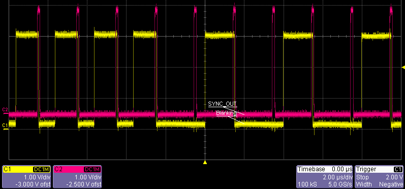
"SPRUGE9E - F2.9.3.2 Event Filtering" states, that blanking windows can overlap, this seem not to be true.
Initialized with the following Code the ePWM generates Sync Pulses @ CTR = Zero and also starts a blanking window @ CTR = Zero. As long as the windows are not overlapping everything is OK, but if you increase the window, that it is longer than the period (i.e. > 120) -> blanking windows overlap and every second window is lost.
Some explanations:
- Blanking (yellow) low means the window is active.
- SYNC_OUT (red) is the sync output @ CTR = Zero
- you can see the blanking window length changed from 50 to 150 in the mid, you would expect to see Blanking to be permanently low from that point, cause the window is longer than the period, but every second window is lost, so that you can see a Blanking at every second pulse that is 2.5µs(150*16,6ns) long.
- to output the blanking window the Output is forced to be low by AQCSFRC, but overwritten by the TripZone that sets it high cause Comp1 @ DCAEVT1 is permanently set. -> Output is low when blanking window inhibits Comp1 @ DCAEVT1
The ePWM init:
//=================================================================================
//    Comparators used for Over Current Trip Zone
//=================================================================================

// init comparators, they will generate a high signal when the input is above the Limit
AdcRegs.ADCCTL1.bit.ADCBGPWD         = 1;                        // Comparator shares the internal BG reference of the ADC -> must be powered even if ADC is unused or uses another reference

Comp1Regs.COMPCTL.bit.COMPDACEN     = 1;                        // Power up Comparator 1
Comp1Regs.COMPCTL.bit.COMPSOURCE     = 0;                          // Connect the inverting input to Internal DAC
Comp1Regs.COMPCTL.bit.CMPINV        = 0;                        // Output is not inverted
Comp1Regs.COMPCTL.bit.QUALSEL        = 0;                        // no Qualification Periode, effectless cause overwritten by SYNCSEL
Comp1Regs.COMPCTL.bit.SYNCSEL        = 0;                        // Asynchronous Comparator Output / Not synchronized to clock
Comp1Regs.DACVAL.bit.DACVAL         = 512;                        // Set DAC output

//=================================================================================
//    ePWM1
//=================================================================================

//DCTRIPSEL
EPwm1Regs.DCTRIPSEL.bit.DCAHCOMPSEL    = DC_COMP1OUT;                // input for Qualifier A High is DC_COMP1OUT

// Event x Qual
EPwm1Regs.TZDCSEL.all                 = 0;                        // init
EPwm1Regs.TZDCSEL.bit.DCAEVT1        = TZ_DCAH_HI;                // forward Comp1 Signal

// init blanking window.
EPwm1Regs.DCFCTL.all                = 0;                        // init
EPwm1Regs.DCFCTL.bit.PULSESEL         = DC_PULSESEL_ZERO;            // alligned @ CTR = Zero
EPwm1Regs.DCFCTL.bit.BLANKE         = DC_BLANK_ENABLE;            // Enable blanking
EPwm1Regs.DCFCTL.bit.SRCSEL         = DC_SRC_DCAEVT1;            // Filter Block signal source (DCAEVT1)
EPwm1Regs.DCFWINDOW                 = 50;                        // Blanking window duration
EPwm1Regs.DCFOFFSET                    = 1;                        // Blanking offset duration

// Event Triggerin
EPwm1Regs.DCACTL.all                = 0;                        // init
EPwm1Regs.DCACTL.bit.EVT1SRCSEL        = DC_EVT_FLT;                // filtered Overcurrent Signal 1
EPwm1Regs.DCBCTL.all                = 0;                        // init

// init, TimeBase is only used to allign the blanking window. Output is controlled by Continous Software Force and TripZone
EPwm1Regs.TBPRD                     = 119;                        // 60MHz / 500kHz - 1 = 119clks;     // Period = 120 TBCLK counts -> 500kHz

EPwm1Regs.TBCTR                     = 0;                         // clear TB counter
EPwm1Regs.TBCTL.bit.CTRMODE         = TB_COUNT_UP;
EPwm1Regs.TBCTL.bit.PHSEN             = TB_DISABLE;                 // Phase loading disabled
EPwm1Regs.TBCTL.bit.PRDLD             = TB_SHADOW;
EPwm1Regs.TBCTL.bit.SYNCOSEL         = TB_CTR_ZERO;                // Output Syny Signal for debug
EPwm1Regs.TBCTL.bit.HSPCLKDIV         = TB_DIV1;                     // TBCLK = SYSCLK
EPwm1Regs.TBCTL.bit.CLKDIV             = TB_DIV1;                    // TBCLK = SYSCLK
EPwm1Regs.TBCTL.bit.PHSDIR            = TB_UP;                    // Count Up after Sync event
EPwm1Regs.TBCTL.bit.FREE_SOFT        = 0x10;                        // Free run even during emulation events

EPwm1Regs.CMPCTL.all                = 0;                        // init

EPwm1Regs.AQCTLA.all                = 0;                        // init
EPwm1Regs.AQCTLB.all                = 0;                        // init

EPwm1Regs.AQSFRC.all                = 0;                        // init
EPwm1Regs.AQSFRC.bit.RLDCSF            = 0x3;                        // Load Continious Software Force immediately

EPwm1Regs.AQCSFRC.all                = 0x0;                        // init
EPwm1Regs.AQCSFRC.bit.CSFA            = AQCSFRC_LOW;                // force Pin state by Software -> low

EPwm1Regs.DBCTL.all                    = 0;                        // DeadBand Control is not used/bypassed

EPwm1Regs.PCCTL.all                    = 0;                        // Chopping is not used/bypassed

// Disable High Resolution
EPwm1Regs.HRCNFG.all                = 0;                        // Disable HR
EPwm1Regs.HRPCTL.all                = 0;

// init Trip Zone
EPwm1Regs.TZSEL.all                    = 0;                        // init

EPwm1Regs.TZCTL.all                    = 0x0FFF;                    // init all Events are disabled
EPwm1Regs.TZCTL.bit.DCAEVT1            = TZ_FORCE_HI;                // OverCurrent Pulse Skipping

EPwm1Regs.TZEINT.all                = 0;                        // init // no Interrupts yet

// Enable TimeBase Clock of the ePWM after they have been configured, to have them synchronized
SysCtrlRegs.PCLKCR0.bit.TBCLKSYNC     = 1;                      // Enable TBCLK within the EPWM

// clear all Flags
EPwm1Regs.TZCLR.all                 = 0x007F;                // Clear all Flags
EPwm2Regs.TZCLR.all                 = 0x007F;                // Clear all Flags
EPwm3Regs.TZCLR.all                 = 0x007F;                // Clear all Flags
EPwm4Regs.TZCLR.all                 = 0x007F;                // Clear all Flags
EPwm1Regs.ETCLR.bit.INT                = 1;                    // Clear Interrupt Flag
EPwm2Regs.ETCLR.bit.INT                = 1;                    // Clear Interrupt Flag
EPwm3Regs.ETCLR.bit.INT                = 1;                    // Clear Interrupt Flag
EPwm4Regs.ETCLR.bit.INT                = 1;                    // Clear Interrupt Flag

// ePWMs are initialized -> route Outputs
GpioCtrlRegs.GPAMUX1.bit.GPIO0         = 1;                    //     0=GPIO,  1=EPWM1A,  2=Resv,       3=Resv

EDIS;


