This thread has been locked.

If you have a related question, please click the "Ask a related question" button in the top right corner. The newly created question will be automatically linked to this question.

Problem with Resolver to Digital Conversion Kit

Hi,

I am using TMDSRSLVR kit to measure angle to use with TMDSHVMTRPFCKIT. But there ware some issues with resolver kit. I have listed them below.

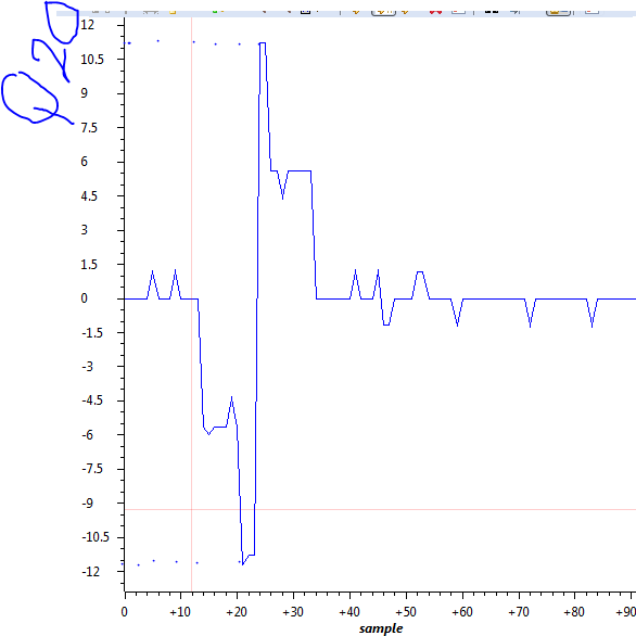
1) I can see only five discrete angle positions from rslvrOut.angleRaw per one resolver cycle. Those are -12, 5, 0, 5, 12,  in iq20 format. And I can not see any other numbers between them. I have attached the graph of rslvrOut.angleRaw for a one resolver cycle.  What should be the problem. Can't I get more angle values smoothly from the TMDSRSLVR kit. 

I am running code with F28069 instead of F28027. 

2) rslvrOut.angleOut is giving completely meaningless data. How can I calibrate that.

3) how can I use that angle to run motor in torque command mode with TMDSHVMTRPFCKIT kit.


Hope you all will help to solve the problem soon.

thanks

  • Hi Lakshan,

    I will move your post to C2000 forum for better support.

    Best regards,
  • Thank you. Hope I will get support soon.
    thanks
  • F28069 has floating point unit, while F28027 has fixed point. You need to use the floating point .lib file?

    rgds,

    ramesh

  • Thank you. solved the problem by using floating point unit. I have another question.

    I can see five resolver cycles per one motor rotation. My pmsm motor has 5 pole pairs.
    But as far as I know, there should be one resolver cycle for one motor rotation. I want to know that whether is this a normal condition or not? If this is a normal condition, what angle should I feed to motor controller park and ipark math block ?

    thanks
  • It is not abnormal. The control designer will have to ensure that the resolver angle zero matches with electrical angle zero, if not, find out the angular offset and subtract it every time you measure the resolver angle before using it.

    rgds,
    ramesh
  • Thank you Ramesh. got the point.
    Can you please explain me how to configure below two parameters in resolver math block. Because I have problem with that.

    resolver1.StepsPerTurn
    resolver1.MechScaler

    I have confused with them.
    what is the steps per turn means. Resolver is showing five cycles per one rotor rotation. that means five times _IQ(0.0) to _IQ(1.0) value sets per one rotor rotation . So resolver1.StepsPerTurn = 5 is corrent ?
    resolver1.MechScaler, mch angle per resolver step means what?
    resolver1.MechScaler = (360/ resolver1.StepsPerTurn) or resolver1.MechScaler = (360/ (resolver1.StepsPerTurn*ADC resolution))

    thanks
  • Dear Rumesh,

    I did not changed MechScaler in the HVMotorCtrl+PfcKit_v2.1\HVPM_Sensored code. I send resolver1.RawTheta through SPI (0 to 0xFFFF for one resolver cycle) and connected that to park angle. But still it wont rotate the motor. Where should be the wrong. my added resolver math block as below,

    I am using BUILDLEVEL LEVEL4 and lsw = 1


    // Initialize resolver module module

    resolver1.StepsPerTurn = 5;
    resolver1.PolePairs = POLES/2;
    resolver1.InitTheta = 0;
    resolver1.MechScaler = 0x00020000;

    in mainISR

    clarke1.As = _IQmpy2(_IQ12toIQ(AdcResult.ADCRESULT1)-offsetA); // Phase A curr.
    clarke1.Bs = _IQmpy2(_IQ12toIQ(AdcResult.ADCRESULT2)-offsetB); // Phase B curr.
    CLARKE_MACRO(clarke1)

    // ------------------------------------------------------------------------------
    // Connect inputs of the PARK module and call the park trans. macro
    // ------------------------------------------------------------------------------
    park1.Alpha = clarke1.Alpha;
    park1.Beta = clarke1.Beta;

    // ------------------------------------------------------------------------------
    // Connect inputs to resolver module
    // ------------------------------------------------------------------------------
    RawThetaSPI = SpiaRegs.SPIDAT;
    resolver1.RawTheta = RawThetaSPI;
    RESOLVER_MACRO (resolver1);


    if(lsw==0) park1.Angle = 0;
    else if(lsw==1) park1.Angle = resolver1.ElecTheta;
    else park1.Angle = resolver1.ElecTheta;

    park1.Sine = _IQsinPU(park1.Angle);
    park1.Cosine = _IQcosPU(park1.Angle);

    PARK_MACRO(park1)


    What should be the wrong ?
    Please help
  • To answer your earlier query:

    Steps per turn is originally conceived for use with QEP, where there would be N (say) edges for every index pulse, that is every rotation. Mechscaler was set up to indicate the mech angle (in pu). When mech angle is multiplied with pole pairs, it gives electrical angle. This code is adapted to resolver and if the resolver resolution is 12 bits, then it will mean 4096 counts per 360 deg electrical. Unlike QEP that gives mech angle first and electrical angle is derived from mech angle, here in resolver, it gives electrical angle of the resolver, and based on the number of pole pairs of the resolver, mech angle should be estimated. In the demo code, the resolver has one pole pair, so it resembles QEP slightly. If the resolver has multiple pole pairs, then without an index pulse kind of information, it is difficult to know the exact mech position of rotor. If position servo control is not needed, then it is no issue. Hope it helps to get the scaling right.

    Make sure that the sense of rotation of motor and resolver are same.  I mean, when you run the motor in open loop, the plot of your resolver feedback and your forced angle should have the same orientation. If they are opposite, the motor will not turn.

    rgds,

    ramesh

  • Dear Rumesh,

    I have a question. As you know, TMDSRSLVR kit shows that resolver angle value between -1 to 1 in pu scale. What is the meaning of that. I have confused with that value. what is the scale. scale is needed to calculate initial angle in pu .
    Is that in between 0 to 360, -360 to 360 or -180 to 180 ?

    Thank you.
  • Hi,

    It is -180 to 180.

    rgds,

    ramesh