This thread has been locked.

If you have a related question, please click the "Ask a related question" button in the top right corner. The newly created question will be automatically linked to this question.

Limited torque and motor hum when increasing Iq Ref

Hi Chris,

We are using a lab5a project with the resolver angle pumped in using the TI's resolver kit. After weeks of work we have the motor controller running smoothly. But while we are trying to increase the torque of the motors, we are seeing the following issues. 

1. After increasing the Iq Ref, is around 20, we see that suddenly the duty cycle goes down  of the PWMs to about  90% or so, and the motor makes a hum, and motor stalls. At this point it draws about 5A. Our current controller is set up to handle 20A,  What could be the issue that its doing this ? Shouldn't the controller be providing 20A or close to that at this much duty cycle ?

2. We also see that we only get a limited amount of torque. While trying to measure stalled torque, our maximum torque is only a fraction of what we are expecting. When increasing Iq Ref, we see the issue in point one above.

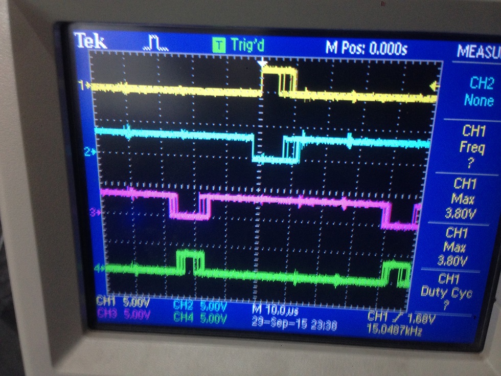
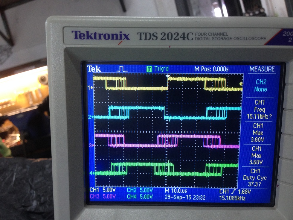
We tried increasing the voltage, but we see the same issue exactly around Iq Ref =20. Below we attach a screen shot of the scope while operating normally and while operating at that 90% duty cycle. This is a PMSM, with our inverter built based on the HVMTRPFCKIT.

Any help is much appreciated. 

  • are you sure in 5a that you have replaced the FAST angle feedback with your resolver feedback?

    "Shouldn't the controller be providing 20A or close to that at this much duty cycle ?"
    That completely depends on the load. The control system only requests the torque (current) that is required for the load.
  • Yes, we think we replaced electrical angle correctly.

    We get electrical angle using resolver and connect it to lab5a as below,

    converted angle 0 to 1 pu in iq24

    in mainISR

     // run the controller

     CTRL_run(ctrlHandle,halHandle,&gAdcData,&gPwmData,Spi_electrical_angle);

    in ctrl.c file

    if(EST_getState(obj->estHandle) >= EST_State_MotorIdentified)

              {

                 // run the online controller

                 // CTRL_runOnLine_User(handle,pAdcData,pPwmData);

                CTRL_runOnLine_User(handle,pAdcData,pPwmData,Spi_electrical_angle_pu);

               }

             else

               {

                 // run the online controller

                 //CTRL_runOnLine(handle,pAdcData,pPwmData);

                 CTRL_runOnLine(handle,pAdcData,pPwmData,Spi_electrical_angle_pu);

               }

    in ctrl.h file both CTRL_runOnLine_User and CTRL_runOnLine functions.

    // generate the motor electrical angle

    // angle_pu = EST_getAngle_pu(obj->estHandle);   // commented for the spi angel

    angle_pu = spi_angle_pu;

    // compute the sin/cos phasor

    CTRL_computePhasor(angle_pu,&phasor);

    Simply we pumped electrical angle to PARK and IPARK modules. Is there a good way to find the initial angle ? after some experiments the motor started to turn smoothly. So we left the initial angle as is. Could that be the problem ?

  • certainly if the angle is incorrect you will not generate the proper torque and under load you would then stall

    it you don't have an absolute resolver you can try to first inject Id current before start-up to force an electrical alignment and zero out your angle. this is shown in proj_lab12 for InstaSPIN_motion. In that lab the RsRecal feature is used (it inject Id current), but in a real system you may want to have your own alignment phase, especially since you aren't using FAST in the CTRL_runOnLine....that may cause an issue trying to run RsRecal.