This thread has been locked.

If you have a related question, please click the "Ask a related question" button in the top right corner. The newly created question will be automatically linked to this question.

TMS320F28027F SPI GPIO as chip select

I want to use a GPIO (specifically GPIO34) as chip select for one of the SPI devices connected to the board. I found a solution here on the forums that involves tying the timing of the custom CS pins to GPIO19, but in my case it's not an option (no free pins). So I tried using SPIATX interrupt to handle CS, but with my implementation the timing is way off (see below).

Here are the signals from the board (red - CLK, blue - MOSI, green - CS[GPIO34]):

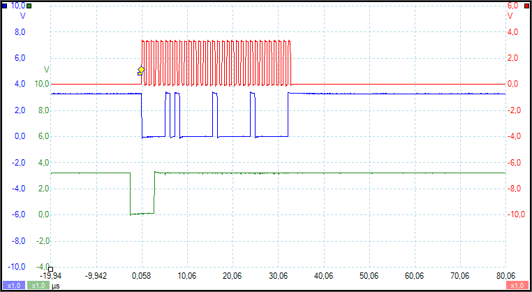
What I'm basically doing here, is:

1. Pull down CS/GPIO34.

2. Writing data (multiple calls to SPI_write8).

3. Enabling the SPIATX interrupt, which pulls CS/GPIO34 back up.

At first I thought it might have something to do with the interrupt being triggered after the first byte being sent, but as you can see in the picture, it's not even waiting for one byte...

Here are the relevant bits of code:

void spi_init(){
    CLK_enableSpiaClock(clkHdl);
    SPI_setCharLength(spiHdl, SPI_CharLength_8_Bits);
    SPI_setMode(spiHdl, SPI_Mode_Master);
    SPI_enableTx(spiHdl);
    SPI_setBaudRate(spiHdl, SPI_BaudRate_1_MBaud);
    SPI_enableLoopBack(spiHdl);
    SPI_enable(spiHdl);
    SPI_setPriority(spiHdl, SPI_Priority_FreeRun);

    return;
}

void spi_fifo_init(){
    SPI_enableChannels(spiHdl);
    SPI_enableFifoEnh(spiHdl);
    SPI_resetTxFifo(spiHdl);
    SPI_clearTxFifoInt(spiHdl);
    SPI_setTxFifoIntLevel(spiHdl, SPI_FifoLevel_4_Words);
    SPI_enableTxFifoInt(spiHdl);
    SPI_resetRxFifo(spiHdl);
    SPI_clearRxFifoInt(spiHdl);
    SPI_setRxFifoIntLevel(spiHdl, SPI_FifoLevel_4_Words);
    SPI_enableRxFifoInt(spiHdl);

    PIE_registerPieIntHandler(pieHdl, PIE_GroupNumber_6, PIE_SubGroupNumber_2, (intVec_t)&spiTxFifoIsr);
    //PIE_enableInt(pieHdl, PIE_GroupNumber_6, PIE_InterruptSource_SPIATX);
    CPU_enableInt(cpuHdl, CPU_IntNumber_6);

    return;
}

interrupt void spiTxFifoIsr(void){
	PIE_disableInt(pieHdl, PIE_GroupNumber_6, PIE_InterruptSource_SPIATX);
	GPIO_setHigh(gpioHdl, GPIO_Number_34);
	SPI_clearTxFifoInt(spiHdl);
	PIE_clearInt(pieHdl, PIE_GroupNumber_6);
}

void setRegister(const uint8_t address, const uint8_t value){
    GPIO_setLow(gpioHdl, GPIO_Number_34);
    SPI_write8(spiHdl, 0x02);
    SPI_write8(spiHdl, address);
    SPI_write8(spiHdl, value);
    PIE_enableInt(pieHdl, PIE_GroupNumber_6, PIE_InterruptSource_SPIATX);
}

Is there a way to make it work with this approach? If not, what do you think of the idea of using timer interrupt based on the length of the data being sent? Any other alternatives that don't use additional pins?

  • Dmitri,

    Your approach could work.
    But Interrupt should be triggered at the right time as per your setting.
    Is there some other place in the code where GPIO34 is being made high?
    Can you place a breakpoint at the beginning of the SPI ISR and check for pin status?

    -Bharathi.

  • I put breakpoint on the first line in spiTxFifoIsr, and the oscilloscope says it's low.
  • Dmitri,

    The SPI TX interrupt will be triggered when the TXFIFO level matches the configured interrupt level which is 4 words according to your configuration.

    You might be able to use a combination of the TXINT and a delay:
    1. set TXXFIFOLVL to 0, so it will interrupt when the final word is transferred to the shift register.
    2. inside of the ISR, the last word will be in the process of transmitting, figure out the time left in the transmission and delay that long
    3. after the necessary delay, set the CS high.

    The other option is to use the RXFIFO interrupt.
    Here, the interrupt will not be triggered until the last word has been received completely. Since you are the master, you know when the final word is fully transmitted. You can then clear the FIFO and then set the CS inactive. If you need the received data, obviously you would read the FIFO, if not, clear it anyway so that there is no overflow error condition.

    I would recommend the second option as it is much more straightforward.


    -Mark
  • But it is triggered before the first byte is finished. I tried setting the TXFIFO level to empty, 1, 2 and 3 words too, and it always looks the same as in the picture.

    So since no matter the configuration, the TXINT is triggered during the first word (rather than the last one as you say should be the case), I would need to adjust the delay based on the amount of data I would be sending. But if I do that, there is no point even having that interrupt. Or do I misunderstand something?

    As for the approach with RX, I have no incoming data (the MISO pin is always high). I just tried it anyways and reconfigured my program to use the RX interrupt instead, and it is never triggered (CS stays low and breakpoint is never hit).