Because of the holidays, TI E2E™ design support forum responses will be delayed from Dec. 25 through Jan. 2. Thank you for your patience.

This thread has been locked.

If you have a related question, please click the "Ask a related question" button in the top right corner. The newly created question will be automatically linked to this question.

about PR controller parameter design in hv_1ph_dcac_board

Hi, I'm studying the PR controller used in voltage source 1ph inverter. I want to know how to design the PR controller parameter in this case, such as kp, ki. Thanks!

  • Jiao,

    PR controller have two criteria 

    1. Stability -. this is ensured by checking OL plot is stable i.e. there is no gain/ less gain when phase crosses over . This is valid for any control system. The compensation designer models this and presents the OL plot which can be used to study this aspect.

    2. Error compensation -> the PR adds very high gain at one frequency trying to reduce that error, however in practical systems the estimation of that frequency can vary, for example the 60Hz grid frequency based on clock of the processor and drifts may be measured as 60.1 or 60.2 , hence some amount of damping is added to the PR controller. To verify if the PR controller is indeed achieving it's goal the error can be measured, however this is rarely needed as just by playing with the proportional and integral gain and damping factor one is able to achiever a stable system with good error compensation.  

  • Hi, Manish,

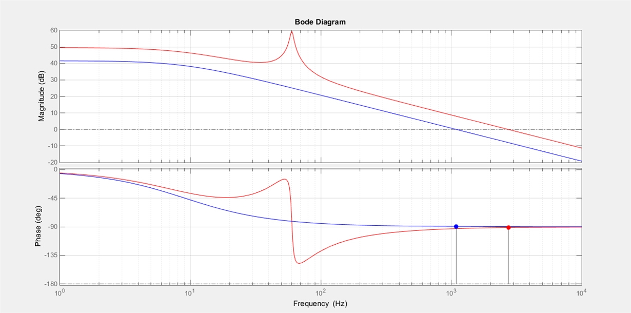
    I've designed a PR controller and plotted the bode diagram. The blue line is the plant, the red line is the open loop diagram. The phase margin is 88.9°@2.74kHz, which is stable. I got the z domain PR controller using tustin

    Gz =

    2.526 z^2 - 4.996 z + 2.471
    ---------------------------
    z^2 - 1.999 z + 0.999

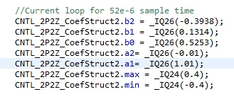
    But when I rewrite these coefficients in 2P2Z controller, it seems that the system begins oscillating. Can you give me some advise about the PR controller? Thanks!

  • Jiao, 

    Are you using a model to determine stability in the above diagram?

    It could be that your model has issues and you really do not have that much BW, PM and GM etc.. 

  • Also i need to mention, i have only tested PR controllers on floating point devices.. not to say there is an issue with fixed point but something i have no experience with
  • Hi, Manish,

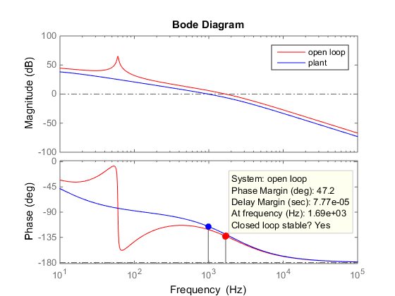
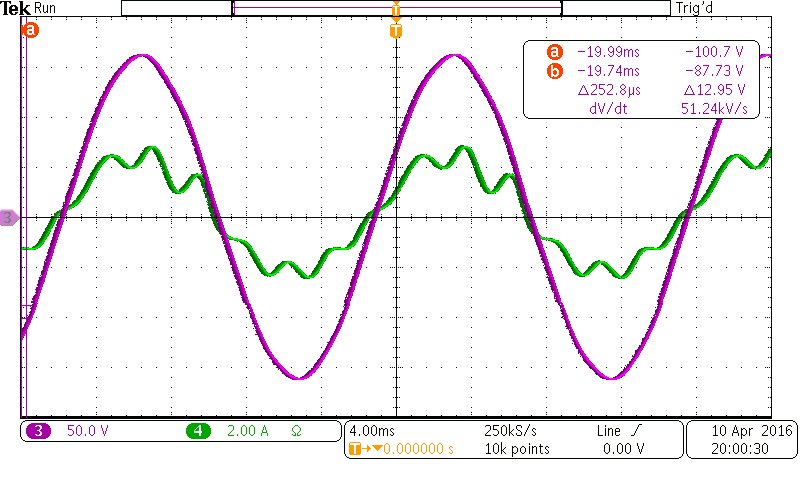
    Thank you for your reply! My circuit is single phase inverter with an LC fitler (TMDSHV1PHINVKIT). My plant model is (Kpwm * Kpwm_1 * Kfi * Kgain_v)/((L * s + r)*(1.5*Ts*s+1)). I designed a PR controller shown below, but it has a lot of 6th and 7th harmonics. When I increased the proportional gain, the fc increased a lot which might made the system oscillate.

    Gz =

     2.031 z^2 - 3.998 z + 1.968

     ---------------------------

       z^2 - 1.999 z + 0.9994