This thread has been locked.

If you have a related question, please click the "Ask a related question" button in the top right corner. The newly created question will be automatically linked to this question.

C2000 (v6.2.11, TMS320F28335): Byte manipulation of 32-bit GPIO

Guru 20045 points


Hello,

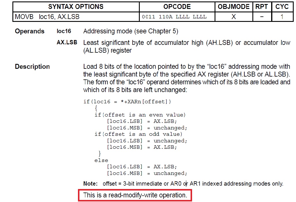
Setting GPIO pins using the DAT register and the byte Intrinsic as shown below is not working.  However, setting the GPIO pins using the SET and CLEAR registers is working. 

What am I doing wrong?

Stephen

Code to set GPIO pins using byte Intrinsic:

    int16 s16Value = (int16)((Uint16)u8DACValue);

    __byte((int16*)&GpioDataRegs.GPADAT.all,0) |= s16Value&0x00001;
    __byte((int16*)&GpioDataRegs.GPADAT.all,0) |= s16Value&0x00002;
    __byte((int16*)&GpioDataRegs.GPADAT.all,0) |= s16Value&0x00004;
    __byte((int16*)&GpioDataRegs.GPADAT.all,0) |= s16Value&0x00008;
    __byte((int16*)&GpioDataRegs.GPADAT.all,0) |= s16Value&0x00010;
    __byte((int16*)&GpioDataRegs.GPADAT.all,0) |= s16Value&0x00020;
    __byte((int16*)&GpioDataRegs.GPADAT.all,0) |= s16Value&0x00040;
    __byte((int16*)&GpioDataRegs.GPADAT.all,0) |= s16Value&0x00080;

Code to set GPIO pins using SET and CLEAR registers:

#define SET_DATA_BUS(u8Value) \
   if (u8Value & 0x0001) \
    { \
        GpioDataRegs.GPASET.bit.GPIO0 = 1; \
    } \
    else \
    { \
        GpioDataRegs.GPACLEAR.bit.GPIO0 = 1; \
    } \
    if (u8Value & 0x0002) \
    { \
        GpioDataRegs.GPASET.bit.GPIO1 = 1; \
    } \
    else \
    { \
        GpioDataRegs.GPACLEAR.bit.GPIO1 = 1; \
    } \
    if (u8Value & 0x0004) \
    { \
        GpioDataRegs.GPASET.bit.GPIO2 = 1; \
    } \
    else \
    { \
        GpioDataRegs.GPACLEAR.bit.GPIO2 = 1; \
    } \
    if (u8Value & 0x0008) \
    { \
        GpioDataRegs.GPASET.bit.GPIO3 = 1; \
    } \
    else \
    { \
        GpioDataRegs.GPACLEAR.bit.GPIO3 = 1; \
    } \
    if (u8Value & 0x0010) \
    { \
        GpioDataRegs.GPASET.bit.GPIO4 = 1; \
    } \
    else \
    { \
        GpioDataRegs.GPACLEAR.bit.GPIO4 = 1; \
    } \
    if (u8Value & 0x0020) \
    { \
        GpioDataRegs.GPASET.bit.GPIO5 = 1; \
    } \
    else \
    { \
        GpioDataRegs.GPACLEAR.bit.GPIO5 = 1; \
    } \
    if (u8Value & 0x0040) \
    { \
        GpioDataRegs.GPASET.bit.GPIO6 = 1; \
    } \
    else \
    { \
        GpioDataRegs.GPACLEAR.bit.GPIO6 = 1; \
    } \
    if (u8Value & 0x0080) \
    { \
        GpioDataRegs.GPASET.bit.GPIO7 = 1; \
    } \
    else \
    { \
        GpioDataRegs.GPACLEAR.bit.GPIO7 = 1; \
    } \

  • How do you know it does not work? Are the bits not set correctly? Are all of them set incorrectly? Just one? Is the order different?
    What are your exact command line options?
  • Hello,

    The code is used to output a sinewave to parallel bus DAC and I am not seeing a sinewave when I set the outputs using the DAT register.

    Do you see anything wrong with the code?

    Stephen 

  • This code is too far removed from what you're seeing for me to make a reasonable guess. I assume you have a companion set of macros to clear the bits in this register that you haven't shown us. If you're expecting a delay between setting individual bits in GPASET, you may need to insert explicit delays.

    You say you do not see a sine wave; what do you see instead?
  • SInce this appears to be specific GPIO behavior, this thread is moved to the C2000 forum.

    Thanks and regards,

    -George

  • Hi Stevenh,

    RMW (read modify write) operation is not recommended for GPIO DAT register. Using SET and CLEAR register for the same is correct method.

    Please see this wiki link for detail info about this.

    Regards,

    Vivek Singh

  • Hello Vivek,

    Ok.

    Then, the following should work since it sets all the lower eight bits of the GPIO DAT register at once.  Am I correct?

    __byte((int16*)&GpioDataRegs.GPADAT.all,0) = s16Value;

    My purpose is to set the GPIO outputs as quickly as possible.

    Thanks,
    Stephen

  • Yes that should work but I am still curious why are you using the __byte intrinsic in this case and not the normal write operation. GPIO module does not support byte accesses.

    Regards,

    Vivek Singh

  • Hello Vivek,

    "Yes that should work but I am still curious why are you using the __byte intrinsic in this case and not the normal write operation. "

    I only want to affect the GIPO port's lowest byte (i.e. GPIO 0 through GPIO1).

    "GPIO module does not support byte accesses."

    Really?  I didn't see anything in SPRUFB0D mentioning that. 

    Stephen

    C-code

    void test3(void)
    {
        volatile int16 s16Value = (int16)((Uint16)u8Value);
    
        __byte((int16*)&GpioDataRegs.GPADAT.all,0) = s16Value;
    
    }

    Assembly:

            test3():
    0090c1:   FE02        ADDB         SP, #2
    0090c2:   761F0300    MOVW         DP, #0x300
    0090c4:   9204        MOV          AL, @0x4
    0090c5:   9641        MOV          *-SP[1], AL
    0090c6:   9241        MOV          AL, *-SP[1]
    0090c7:   8F006FC0    MOVL         XAR4, #0x006fc0
    0090c9:   3CC4        MOVB         *+XAR4[0], AL.LSB
    0090ca:   FE82        SUBB         SP, #2
    0090cb:   0006        LRETR        

  • Hi Stephen,

    C28x is 16bit machine. It does not support byte access and so the peripherals.

    MOVB instruction (byte intrinsic) is actually READ modify WRITE (RMW) instruction to update the 8bit.  As I mentioned earlier, RMW operation should be avoided with GPIO DAT register and use SET/CLEAR register instead.

    Regards,

    Vivek Singh

  • Hello Vivek,

    I am confused by what your are saying.  First you said it doesn't support byte access and then you said the MOVB instruction updates the 8-bits.

    From what I understand, there are only two concerns with RMW operations:

    1. Time Delay - The pipeline and Read/Modify/Write adds a delay, which can affect the setting/reading of the register after the RMW is started.

    2. Data corruption - A bit or bits in the register that are being accessed could be updated from some other source (isr or ect.) while a specific bit/bits is being changed. 

    The 2nd one is not an issued If the byte instruction can be used to update the lower 8-bits of the register without affecting the other parts of the register.  You seem to confirm this is true in your last post.

    The 1st one is not an issue since I simultaneously update all the bits in GPIOA register's lower 8-bit every 100us.

    Do you agree?

    Stephen


  • Stephen,

    The MOVB instruction is actually a read modify instruction. CPU will  read 16bit, update the byte which need to written and then again do a 16bit write. This is how it updates the 8bits.

    If you have enough time difference between two successive write then I agree, #1 may not be concern for you. But why don't you want to use the SET/CLEAR register? So you see any issue with that?

    Regards,

    Vivek Singh

  • Hello Vivek,

    "The MOVB instruction is actually a read modify instruction. CPU will  read 16bit, update the byte which need to written and then again do a 16bit write. This is how it updates the 8bits."

    According the the TMS320F28X CPU instruction set and reference guide (SPRU430F) shown below, the instruction only affects the lower 8-bits. Therefore, only the low 8-bits of the 32-bit register would be affected.  Is that correct?

    "But why don't you want to use the SET/CLEAR register? So you see any issue with that?"

    I want to optimize and simplify my code.  The SET_DATA_BUS macro in my original post is overly complex and slow.

    The data bus is interfaced to a parallel DAC.  For the chip selects and write signals I use the GPIO SET and CLEAR registers.

    Stephen

  • Hello Vivek,

    In the instruction description for the MOVB instruction, what does "unchanged" mean?  

    Does that mean that the other part of the 16-bit register is not written at all?

    I would think so because the description says "load 8-bits of the location pointed to by location "loc16" addressing mode...."

    Testing the scenario where 16-bits are loaded back into the register would be impossible to do.

    Stephen

  • Hi Stephen,

    Unchanged means it'll be written back with the same data. For example if register had value 0x1255 and you are tying to change the 8bit LSB (8bit) to 0x55 then value 0x12AA will be written back.

    If you look at the definition of the MOVB instruction (which you posted earlier), it clearly says that it's a Read Modify Write operation.

    Please go through this link as well which has more detail on this.

    Regards,

    Vivek Singh

  • Hello Vivek,

    The reference guide needs to be updated to be more explicit, e.g. it could mentioned that the whole 16-bit is written.  Also, The reference guide doesn't describe the read-modify-write operation.  Of course the wiki that you mentioned to me describes something, but it's not enough to give a clear picture of what's going on.  

    What does "There is, however, some delay between a write to the DAT register and when the resulting value will be seen on the pin and then reflected back to the DAT." exactly mean?  What reference guide has that information?

    I am intending to use the byte operation to write all the port bits at once (GPI0 to GPIO7).  The GPIO8 through GPIO15 perform the chip selects,write/read line and DAC port A/B select functions.  I will use the GPIO SET and CLEAR registers for the those function.

    The MOVB is a single CPU instruction and only takes 1 clock cycle to complete. Therefore, before my code sets or clears a GPIO register associated with either the chip select, write/read line or DAC port  A/B section function, the GPIO DAT register should have already been updated.  Is that correct?

    Stephen 

  • Stephen,

    for 1, there will be some read then modify write even for the byte intrinsic.

    for 2, the SET and CLEAR registers will ignore any "0" values written. A "1" will set if using the SET register, a "1" will clear if using the CLEAR register. Both ignore any "0" written.

    The SET and CLEAR registers are the most straight forward way to write to GPIO as fast as possible.

    Cheers
    Lori
  • Hello Lori,

    For my situation, I am thinking I don't have to worry about the read modify write issue.

    The Write to DAC code flow will be as follows:

        1. Set all bits at once using the  __byte((int16*)&GpioDataRegs.GPADAT.all,0) = s16Value;

        2. Set the DAC Port select (i.e. A or B DAC port) using GPIO SET or CLEAR register.

        3. Set the DAC Chip select low  using GPIO SET or CLEAR register.

        4. Toggle DAC write low using GPIO SET or CLEAR register.

        5. Toggle DAC write high using GPIO SET or CLEAR register.

        6. Set the DAC Chip select high using GPIO SET or CLEAR register

    There will be some delays between those operation to take into account the DAC specification timing.  I am using the GPIO range GPIO8-GPIO15 for part 2) through 6) above.  I believe the the byte write in 1) won't affect the bit writes to the SET and CLEAR registers in 2) through 6). Do you agree?  Also, there is no other place in the code that writes to the DAC data bus.

    "The SET and CLEAR registers are the most straight forward way to write to GPIO as fast as possible."

    How is writing each bit faster than writing all 8-bits at once. 

    If there is some reason there is a issue with writing to the DAC data bus using the GPIO DAT, I guess I could do the following, which would be faster than using all those if constructs in the SET_DATA_BUS macro.

    __byte((int16*)&GpioDataRegs.GPASET.all,0) = s16Value;
    __byte((int16*)&GpioDataRegs.GPACLEAR.all,0) =  (s16Value^0x00FF)&0x00FF // XOR toggles all 0 value bits to 1s.
    

    What do you think?

    However, I would first like to know if there are any issues with the way I am using the DAT register.

    Stephen

  • Hi Stephen,

    How is writing each bit faster than writing all 8-bits at once. 

    It's not faster but simpler. If you are using data register then of course it'll be faster because you can set as well clear using single write. As mentioned earlier, if you think that in your application the way you are modifying DAT register, it'll not have the issues explained then you can use the DAT register.

    Also please note that SET and CLEAR register bit have effect when written as '1' and write '0' has no impact (also read returns 0x0) so you don't have to use the byte intrinsic for these. You can just write '1' to the bits for the GPIO which need to be updated and rest all will remain unchanged. There is also TOGGLE register which can be used to toggle the state of GPIO pin if needed.

    Regards,

    Vivek Singh

  • stevenh said:
    How is writing each bit faster than writing all 8-bits at once. 

    You can set or clear as many bits as you like using the .all. 

    For example, the following line will pull all pins corresponding to "1" in s16Value high, and ignore any "0" values.

    GpioDataRegs.GPASET.all = s16Value


  • Hello Lori,

    Ok.  

    I'll use the SET and CLEAR the way I mentioned in my previous post, i.e.

    __byte((int16*)&GpioDataRegs.GPASET.all,0) = s16Value&0xFF;
    __byte((int16*)&GpioDataRegs.GPACLEAR.all,0) =  (s16Value^0x00FF)&0x00FF // XOR toggles all 0 value bits to 1s.

    Even though the SET and CLEAR only modify the specified bits, I will still use the __byte intrinsic so there's no possibility of the upper 16-bits being modified.

    I Previously didn't realize all the bits in the SET or CLEAR register could be respectively set or cleared at once.

    Thanks,

    Stephen