


Hello,
I'm trying to run a example of LAUNCHXL -F28027F with ccs v6.
But it seems like not work well.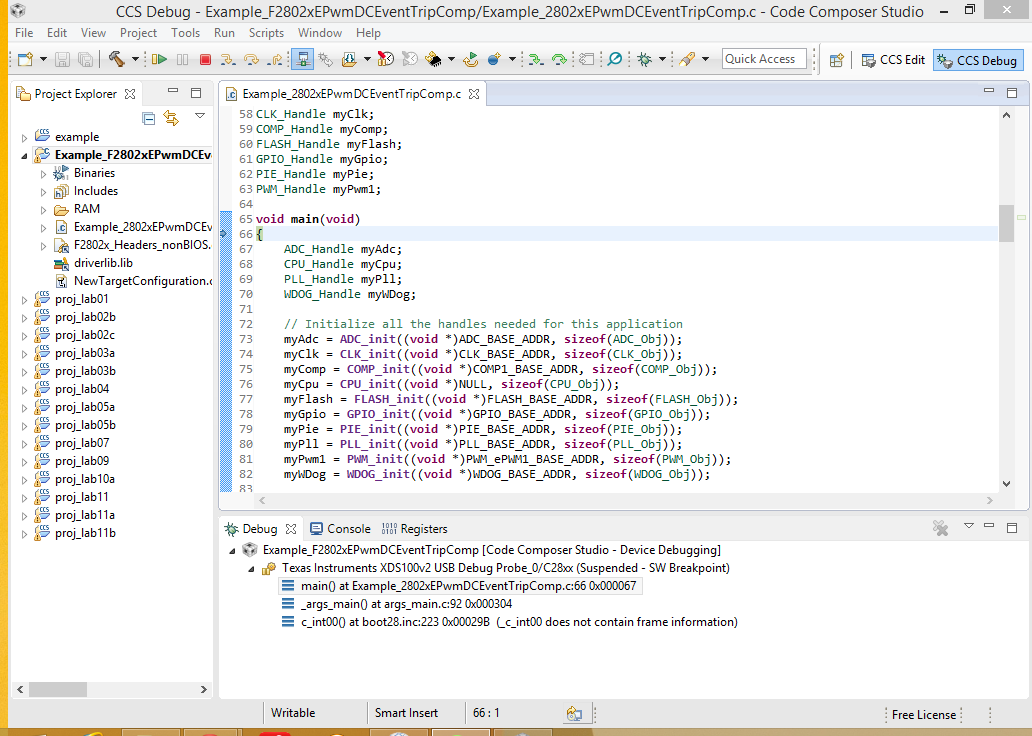
And this is a example so i don't know whether it is a debug session.
this is "main"
//#############################################################################
//
// File: f2802x_examples_ccsv4/epwm_dcevent_trip_comp/Example_F2802xEpwmTripZoneComp.c
//
// Title: Check PWM Trip Zone Test with Comparator Inputs
//
// Group: C2000
// Target Device: TMS320F2802x
//
//! \addtogroup example_list
//! <h1>PWM Trip Zone Test with Comparator Inputs</h1>
//!
//! This example configures ePWM1 and its associated trip zone.
//!
//! Initially make voltage on pin COMP1A greater than COMP1B if using
//! dual pin compare; else make internal DAC output lower than V on COMP1A.
//!
//! During the test, monitor ePWM1 outputs on a scope.
//! Increase the voltage on inverting side of comparator(either through COMP1B
//! pin or internal DAC setting) to trigger a DCAEVT1, and DCBEVT1.
//!
//! EPWM1A is on GPIO0 \n
//! EPWM1B is on GPIO1
//!
//! DCAEVT1, DCBEVT1 a are all defined as true when COMP1OUT is low.
//!
//! ePWM1 will react to DCAEVT1 and DCBEVT1 as a 1 shot trip.
//! DCAEVT1 will pull EPWM1A high.
//! DCBEVT1 will pull EPWM1B low .
//
//
// (C) Copyright 2012, Texas Instruments, Inc.
//#############################################################################
// $TI Release: LaunchPad f2802x Support Library v100 $
// $Release Date: Wed Jul 25 10:45:39 CDT 2012 $
//#############################################################################
#include "DSP28x_Project.h" // Device Headerfile and Examples Include File
#include "f2802x_common/include/adc.h"
#include "f2802x_common/include/clk.h"
#include "f2802x_common/include/comp.h"
#include "f2802x_common/include/flash.h"
#include "f2802x_common/include/gpio.h"
#include "f2802x_common/include/pie.h"
#include "f2802x_common/include/pll.h"
#include "f2802x_common/include/pwm.h"
#include "f2802x_common/include/wdog.h"
// Prototype statements for functions found within this file.
void InitEPwm1Example(void);
interrupt void epwm1_tzint_isr(void);
// Global variables used in this example
uint32_t EPwm1TZIntCount;
uint32_t EPwm2TZIntCount;
CLK_Handle myClk;
COMP_Handle myComp;
FLASH_Handle myFlash;
GPIO_Handle myGpio;
PIE_Handle myPie;
PWM_Handle myPwm1;
void main(void)
{
ADC_Handle myAdc;
CPU_Handle myCpu;
PLL_Handle myPll;
WDOG_Handle myWDog;
// Initialize all the handles needed for this application
myAdc = ADC_init((void *)ADC_BASE_ADDR, sizeof(ADC_Obj));
myClk = CLK_init((void *)CLK_BASE_ADDR, sizeof(CLK_Obj));
myComp = COMP_init((void *)COMP1_BASE_ADDR, sizeof(COMP_Obj));
myCpu = CPU_init((void *)NULL, sizeof(CPU_Obj));
myFlash = FLASH_init((void *)FLASH_BASE_ADDR, sizeof(FLASH_Obj));
myGpio = GPIO_init((void *)GPIO_BASE_ADDR, sizeof(GPIO_Obj));
myPie = PIE_init((void *)PIE_BASE_ADDR, sizeof(PIE_Obj));
myPll = PLL_init((void *)PLL_BASE_ADDR, sizeof(PLL_Obj));
myPwm1 = PWM_init((void *)PWM_ePWM1_BASE_ADDR, sizeof(PWM_Obj));
myWDog = WDOG_init((void *)WDOG_BASE_ADDR, sizeof(WDOG_Obj));
// Perform basic system initialization
WDOG_disable(myWDog);
CLK_enableAdcClock(myClk);
(*Device_cal)();
CLK_disableAdcClock(myClk);
//Select the internal oscillator 1 as the clock source
CLK_setOscSrc(myClk, CLK_OscSrc_Internal);
// Setup the PLL for x10 /2 which will yield 50Mhz = 10Mhz * 10 / 2
PLL_setup(myPll, PLL_Multiplier_10, PLL_DivideSelect_ClkIn_by_2);
// Disable the PIE and all interrupts
PIE_disable(myPie);
PIE_disableAllInts(myPie);
CPU_disableGlobalInts(myCpu);
CPU_clearIntFlags(myCpu);
// If running from flash copy RAM only functions to RAM
#ifdef _FLASH
memcpy(&RamfuncsRunStart, &RamfuncsLoadStart, (size_t)&RamfuncsLoadSize);
#endif
// For this case just init GPIO pins for ePWM1
GPIO_setPullUp(myGpio, GPIO_Number_0, GPIO_PullUp_Disable);
GPIO_setPullUp(myGpio, GPIO_Number_1, GPIO_PullUp_Disable);
GPIO_setMode(myGpio, GPIO_Number_0, GPIO_0_Mode_EPWM1A);
GPIO_setMode(myGpio, GPIO_Number_1, GPIO_1_Mode_EPWM1B);
// Setup a debug vector table and enable the PIE
PIE_setDebugIntVectorTable(myPie);
PIE_enable(myPie);
// Register interrupt handlers in the PIE vector table
PIE_registerPieIntHandler(myPie, PIE_GroupNumber_2, PIE_SubGroupNumber_1, (intVec_t)&epwm1_tzint_isr);
// Enable Clock to the ADC
CLK_enableAdcClock(myClk);
// Comparator shares the internal BG reference of the ADC, must be powered even if ADC is unused
ADC_enableBandGap(myAdc);
// Delay to allow BG reference to settle.
DELAY_US(1000L);
// Enable clock to the Comparator 1 block
CLK_enableCompClock(myClk, CLK_CompNumber_1);
// Power up Comparator 1 locally
COMP_enable(myComp);
// Connect the inverting input to pin COMP1B
COMP_disableDac(myComp);
////////////////Uncomment following 4 lines to use DAC instead of pin COMP1B //////////////////
// // Connect the inverting input to the internal DAC
// COMP_enableDac(myComp);
// // Set DAC output to midpoint
// COMP_setDacValue(myComp, 512);
//////////////////////////////////////////////////////////////////////////////////////////////
CLK_disableTbClockSync(myClk);
InitEPwm1Example();
CLK_enableTbClockSync(myClk);
// Initalize counters
EPwm1TZIntCount = 0;
// Enable CPU INT3 which is connected to EPWM1-3 INT
CPU_enableInt(myCpu, CPU_IntNumber_2);
// Enable EPWM INTn in the PIE: Group 2 interrupt 1-3
PIE_enablePwmTzInt(myPie, PWM_Number_1);
// Enable global Interrupts and higher priority real-time debug events
CPU_enableGlobalInts(myCpu);
CPU_enableDebugInt(myCpu);
for(;;) {
asm(" NOP");
}
}
interrupt void epwm1_tzint_isr(void)
{
EPwm1TZIntCount++;
// Leave the PWM flags set so we only take this
// interrupt once
// Acknowledge this interrupt to receive more interrupts from group 2
PIE_clearInt(myPie, PIE_GroupNumber_2);
}
void InitEPwm1Example()
{
CLK_enablePwmClock(myClk, PWM_Number_1);
PWM_setPeriod(myPwm1, 8000); // Set timer period
PWM_setPhase(myPwm1, 0x0000); // Phase is 0
PWM_setCount(myPwm1, 0x0000);
// Setup TBCLK
PWM_setCounterMode(myPwm1, PWM_CounterMode_UpDown); // Count up/down
PWM_disableCounterLoad(myPwm1); // Disable phase loading
PWM_setHighSpeedClkDiv(myPwm1, PWM_HspClkDiv_by_4); // Clock ratio to SYSCLKOUT
PWM_setClkDiv(myPwm1, PWM_ClkDiv_by_4);
PWM_setShadowMode_CmpA(myPwm1, PWM_ShadowMode_Shadow); // Load registers every ZERO
PWM_setShadowMode_CmpB(myPwm1, PWM_ShadowMode_Shadow);
PWM_setLoadMode_CmpA(myPwm1, PWM_LoadMode_Zero);
PWM_setLoadMode_CmpB(myPwm1, PWM_LoadMode_Zero);
// Setup compare
PWM_setCmpA(myPwm1, 3000);
// Set actions
PWM_setActionQual_CntUp_CmpA_PwmA(myPwm1, PWM_ActionQual_Set);
PWM_setActionQual_CntDown_CmpA_PwmA(myPwm1, PWM_ActionQual_Clear);
PWM_setActionQual_CntUp_CmpA_PwmB(myPwm1, PWM_ActionQual_Clear);
PWM_setActionQual_CntDown_CmpA_PwmB(myPwm1, PWM_ActionQual_Set);
// Define an event (DCAEVT1) based on TZ1 and TZ2
PWM_setDigitalCompareInput(myPwm1, PWM_DigitalCompare_A_High, PWM_DigitalCompare_InputSel_COMP1OUT); // DCAH = Comparator 1 output
PWM_setDigitalCompareInput(myPwm1, PWM_DigitalCompare_A_Low, PWM_DigitalCompare_InputSel_TZ2); // DCAL = TZ2
PWM_setTripZoneDCEventSelect_DCAEVT1(myPwm1, PWM_TripZoneDCEventSel_DCxHL_DCxLX); // DCAEVT1 = DCAH low(will become active as Comparator output goes low)
PWM_setDigitalCompareAEvent1(myPwm1, false, true, false, false); // DCAEVT1 = DCAEVT1 (not filtered), Take async path
// Define an event (DCBEVT1) based on TZ1 and TZ2
PWM_setDigitalCompareInput(myPwm1, PWM_DigitalCompare_B_High, PWM_DigitalCompare_InputSel_COMP1OUT); // DCBH = Comparator 1 output
PWM_setDigitalCompareInput(myPwm1, PWM_DigitalCompare_B_Low, PWM_DigitalCompare_InputSel_TZ2); // DCAL = TZ2
PWM_setTripZoneDCEventSelect_DCBEVT1(myPwm1, PWM_TripZoneDCEventSel_DCxHL_DCxLX); // DCBEVT1 = (will become active as Comparator output goes low)
PWM_setDigitalCompareBEvent1(myPwm1, false, true, false, false); // DCBEVT1 = DCBEVT1 (not filtered), Take async path
// Enable DCAEVT1 and DCBEVT1 are one shot trip sources
// Note: DCxEVT1 events can be defined as one-shot.
// DCxEVT2 events can be defined as cycle-by-cycle.
PWM_enableTripZoneSrc(myPwm1, PWM_TripZoneSrc_OneShot_CmpA);
PWM_enableTripZoneSrc(myPwm1, PWM_TripZoneSrc_OneShot_CmpB);
// What do we want the DCAEVT1 and DCBEVT1 events to do?
// DCAEVTx events can force EPWMxA
// DCBEVTx events can force EPWMxB
PWM_setTripZoneState_TZA(myPwm1, PWM_TripZoneState_EPWM_High); // EPWM1A will go high
PWM_setTripZoneState_TZB(myPwm1, PWM_TripZoneState_EPWM_Low); // EPWM1B will go low
// Enable TZ interrupt
PWM_enableTripZoneInt(myPwm1, PWM_TripZoneFlag_OST);
}
//===========================================================================
// No more.
//===========================================================================
thank you very much!

