This thread has been locked.

If you have a related question, please click the "Ask a related question" button in the top right corner. The newly created question will be automatically linked to this question.

Miss the file angle.h in Motorware 15?

Other Parts Discussed in Thread: MOTORWARE, CONTROLSUITE

Dear Motorware Team,

I read in MotorWare Explorer Version 01_01_00_15  and know that: there is module ANGLE_Obj that is defined in the file angle.h as a following figure:
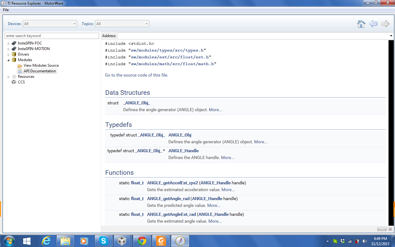
But when I took a search this module to include into my project, I did not find it!!! 

Please let me know where I can link to this module to my project.

Another question is how to use this module?

Thank you very much.

Tran,

  • Hi Tran,

    I understand you want to know how to use this module, but let me ask what are trying to do in your application?  Do you need to get the rotor angle from the FAST observer?

    If so, why not use one of the EST_getAngle functions?

    Jeff

  • Dear Jeff,

    Thank you for your responding to my question. I am intending to use ANGLE module to generating a angle in order for testing a motor with the open-loop V/f control firstly. I want to develop my project safely with Motorware library in the manner ControlSuite project did, it means that I want to build my project with many level.

    LEVEL #1: to check Pwm and Svgen with V/f open-loop control

    LEVEL #2: to check Adc reading and clarke, park transformation

    LEVEL #3: to check FAST Estimator (in Lab 11)

    LEVEL #4: to check the system with current controller

    LEVEL #5: to check the system with speed controller

    LEVEL #6: to check the system with full features including protection and state machine of my product for controlling a motor.

    And I hope Motorware can help me to do this in manner of systematic. 

    If you have any idea to help me, please give me some advise. I highly appreciate your ideas. 

    Tran,

  • Hi Tran,

    The angle module was accidentally released with MotorWare 15 is actually part of a later MotorWare release that is in development.  Please do not use the angle module, it will not work with the current MW structure and will only cause you trouble.  All of the functions you need to get the angle information are available in the EST functions.

    I like your structured approach of the 6 levels, this is very much like the ControlSUITE examples.  for MotorWare we are implementing some "Ease-of-Use" solutions and forum feedback like yours is used as reference for our work.  Thank you for the feedback.

    Jeff

  • Dear Jeff,

    I am trying to develop my project with motorware based on Lab11. I intend to test and make sure the operation of every module when working with motorware, so that I must go from the bottom to the top.

    Firstly I want to check modules: SVGEN, PWM, PWMDAC, DLOG without connection to the motor or the IGBT power module. So that I cannot take the "angle_pu" signal from Estimator module, because the EST functions only work when you connect to the ADC module and the motor as well as you must supply the power to IGBT power hardware.

    In the ControlSuite, an example has a solution as following:

    // =============================== LEVEL 1 ======================================
    //	  Checks target independent modules, duty cycle waveforms and PWM update
    //	  Keep the motors disconnected at this level!	
    // ==============================================================================
    
    #if (BUILDLEVEL==LEVEL1)	 
    
    // ------------------------------------------------------------------------------
    //  Connect inputs of the RMP module and call the ramp control macro
    // ------------------------------------------------------------------------------
        rc1.TargetValue = SpeedRef;		
    	RC_MACRO(rc1)
    
    // ------------------------------------------------------------------------------
    //  Connect inputs of the RAMP GEN module and call the ramp generator macro
    // ------------------------------------------------------------------------------
        rg1.Freq = rc1.SetpointValue;
    	RG_MACRO(rg1)
    
    // ------------------------------------------------------------------------------
    //  Connect inputs of the INV_PARK module and call the inverse park trans. macro
    //	There are two option for trigonometric functions:
    //  IQ sin/cos look-up table provides 512 discrete sin and cos points in Q30 format
    //  IQsin/cos PU functions interpolate the data in the lookup table yielding higher resolution. 
    // ------------------------------------------------------------------------------
        ipark1.Ds = VdTesting;
        ipark1.Qs = VqTesting;
        
    	//ipark1.Sine  =_IQ30toIQ(IQsinTable[_IQtoIQ9(rg1.Out)]);
        //ipark1.Cosine=_IQ30toIQ(IQcosTable[_IQtoIQ9(rg1.Out)]);
    
    	ipark1.Sine=_IQsinPU(rg1.Out);
        ipark1.Cosine=_IQcosPU(rg1.Out);
    	IPARK_MACRO(ipark1)
    
    // ------------------------------------------------------------------------------
    //  Connect inputs of the SVGEN module and call the space-vector gen. macro
    // ------------------------------------------------------------------------------
      	svgen1.Ualpha = ipark1.Alpha;
     	svgen1.Ubeta  = ipark1.Beta;	
    	SVGENDQ_MACRO(svgen1)   
    
    // ------------------------------------------------------------------------------
    //  Connect inputs of the PWM_DRV module and call the PWM signal generation macro
    // ------------------------------------------------------------------------------
        pwm1.MfuncC1 = svgen1.Ta;  
        pwm1.MfuncC2 = svgen1.Tb;   
        pwm1.MfuncC3 = svgen1.Tc; 
    	PWM_MACRO(1,2,3,pwm1)							// Calculate the new PWM compare values	
    
    // ------------------------------------------------------------------------------
    //    Connect inputs of the PWMDAC module 
    // ------------------------------------------------------------------------------	
    	pwmdac1.MfuncC1 = svgen1.Ta; 
        pwmdac1.MfuncC2 = svgen1.Tb; 
        PWMDAC_MACRO(6,pwmdac1)	  						// PWMDAC 6A, 6B
        
        pwmdac1.MfuncC1 = svgen1.Tc; 
        pwmdac1.MfuncC2 = svgen1.Tb-svgen1.Tc; 
    	PWMDAC_MACRO(7,pwmdac1)		  					// PWMDAC 7A, 7B  
    
    // ------------------------------------------------------------------------------
    //    Connect inputs of the DATALOG module 
    // ------------------------------------------------------------------------------
        DlogCh1 = (int16)_IQtoIQ15(svgen1.Ta);
        DlogCh2 = (int16)_IQtoIQ15(svgen1.Tb);
        DlogCh3 = (int16)_IQtoIQ15(svgen1.Tc);
        DlogCh4 = (int16)_IQtoIQ15(svgen1.Tb-svgen1.Tc);
    
    #endif // (BUILDLEVEL==LEVEL1)

    For the LEVEL #2, they did as following:

    // =============================== LEVEL 2 ======================================
    //	  Level 2 verifies the analog-to-digital conversion, offset compensation, 
    //    clarke/park transformations (CLARKE/PARK), 
    // ==============================================================================
    
    #if (BUILDLEVEL==LEVEL2) 
    
    
    // ------------------------------------------------------------------------------
    //  Connect inputs of the RMP module and call the ramp control macro
    // ------------------------------------------------------------------------------
        rc1.TargetValue = SpeedRef;		
    	RC_MACRO(rc1)
    
    // ------------------------------------------------------------------------------
    //  Connect inputs of the RAMP GEN module and call the ramp generator macro
    // ------------------------------------------------------------------------------
        rg1.Freq = rc1.SetpointValue;
    	RG_MACRO(rg1) 
    		
    // ------------------------------------------------------------------------------
    //  Measure phase currents, subtract the offset and normalize from (-0.5,+0.5) to (-1,+1). 
    //	Connect inputs of the CLARKE module and call the clarke transformation macro
    // ------------------------------------------------------------------------------
    	clarke1.As = _IQmpy2(_IQ12toIQ(AdcResult.ADCRESULT1)-offsetA); // Phase A curr.
    	clarke1.Bs = _IQmpy2(_IQ12toIQ(AdcResult.ADCRESULT2)-offsetB); // Phase B curr.	
    	CLARKE_MACRO(clarke1) 
    	
    // ------------------------------------------------------------------------------
    //  Connect inputs of the PARK module and call the park trans. macro
    // ------------------------------------------------------------------------------
    	park1.Alpha  = clarke1.Alpha;
    	park1.Beta   = clarke1.Beta;
    	park1.Angle  = rg1.Out;
    	park1.Sine   = _IQsinPU(park1.Angle);
    	park1.Cosine = _IQcosPU(park1.Angle);
    	PARK_MACRO(park1) 
     
    // ------------------------------------------------------------------------------
    //	Connect inputs of the INV_PARK module and call the inverse park trans. macro
    // ------------------------------------------------------------------------------
        ipark1.Ds    = VdTesting;
        ipark1.Qs    = VqTesting;
    	ipark1.Sine  = park1.Sine;
        ipark1.Cosine= park1.Cosine;
    	IPARK_MACRO(ipark1) 
    	
    // ------------------------------------------------------------------------------
    //  Connect inputs of the SVGEN module and call the space-vector gen. macro
    // ------------------------------------------------------------------------------
      	svgen1.Ualpha = ipark1.Alpha;
     	svgen1.Ubeta  = ipark1.Beta;	
    	SVGENDQ_MACRO(svgen1)
    
    // ------------------------------------------------------------------------------
    //  Connect inputs of the PWM_DRV module and call the PWM signal generation macro
    // ------------------------------------------------------------------------------
        pwm1.MfuncC1 = svgen1.Ta;  
        pwm1.MfuncC2 = svgen1.Tb;   
        pwm1.MfuncC3 = svgen1.Tc; 
    	PWM_MACRO(1,2,3,pwm1)							// Calculate the new PWM compare values	
    
    // ------------------------------------------------------------------------------
    //    Connect inputs of the PWMDAC module 
    // ------------------------------------------------------------------------------	
    	pwmdac1.MfuncC1 = clarke1.As; 
        pwmdac1.MfuncC2 = clarke1.Bs; 
        PWMDAC_MACRO(6,pwmdac1)	  						// PWMDAC 6A, 6B
        
        pwmdac1.MfuncC1 = rg1.Out; 
        pwmdac1.MfuncC2 = svgen1.Ta; 
    	PWMDAC_MACRO(7,pwmdac1)		  					// PWMDAC 7A, 7B  
    
    // ------------------------------------------------------------------------------
    //    Connect inputs of the DATALOG module 
    // ------------------------------------------------------------------------------
        DlogCh1 = (int16)_IQtoIQ15(clarke1.As);
        DlogCh2 = (int16)_IQtoIQ15(clarke1.Bs);
        DlogCh3 = (int16)_IQtoIQ15(rg1.Out);
        DlogCh4 = (int16)_IQtoIQ15(svgen1.Ta);
    
    
    #endif // (BUILDLEVEL==LEVEL2)
    

    And so on...

    Because I am developing my project on my own motor driven hardware (not TI's development kit) so that I must test carefully each modules of Motorware and I cannot apply the EST functions at LEVEL #1 and LEVEL #2 at the moment.

    If you have any ideas to resolve my problem, please give me an advice.

    Thank you very much,

    Tran