This thread has been locked.

If you have a related question, please click the "Ask a related question" button in the top right corner. The newly created question will be automatically linked to this question.

Hall Sensor data in DRV8312GUI_Main.c

Other Parts Discussed in Thread: CONTROLSUITE

I am using the 8-pole NEMA17 Motor that came with the DRV8312-C2 Kit. I loaded the DRV8312GUI_Main.c and set to run with BLDC Sensored (Motor Type 2). I then adjusted the GUISpeedRef to obtain a low RPM (about 250 RPM). I noticed that the hall sensor pulses are not of same length anymore. 

What could be the cause for this?

I tested the motor using the InstapSPIN BLDC Gui, set to run about 0.04 PU or 250 RPM. Below is the plot. As you can see, the Hall sensor pulses are of same length.

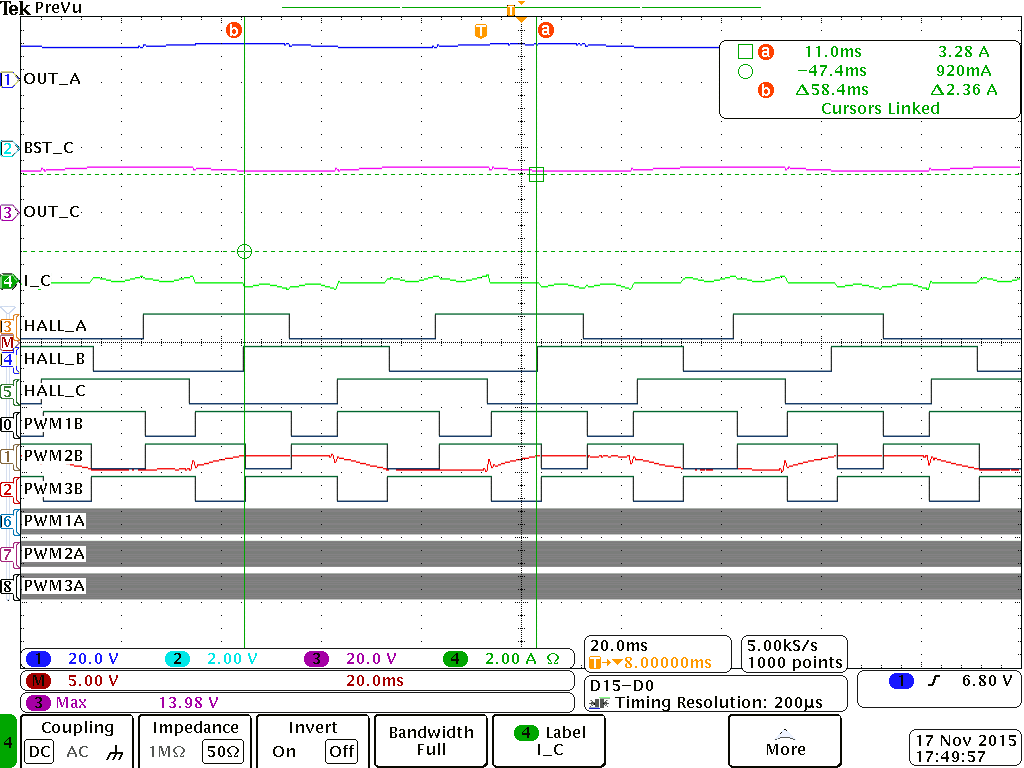
InstaSPIN BLDC doesnt use Hall Sensor data but based on the oscilloscope graph (the 2nd one), it shows that the motor runs smoothly. For the first oscilloscope graph, the motor is not running that smooth? 

Can somebody shed light to this issue? What needs to be done to correct this?

  • From the first plot it looks like the commutation algorithm you are using probably needs to add some filtering to the hall effect sensor inputs. Or the speed controller you are using maybe needs some tuning to keep the speed constant, or maybe your speed calculation from hall sensor inputs needs some work to provide a constant speed from the hall sensor inputs.

  • Thanks for the response.

    The code I used when i got the uneven Hall Sensor pulses is the one from ControlSuite. I have not altered the code DRV8312GUI_Main.c. I only changed the value of the variable GUISpeedRef to set it to a low RPM.

    One thing I noticed is that in the GUI that came with the USB-Stick of DRV8312-C2 Kit (the DRV8312GUIv5.exe), the minimum RPM that can be set is 600 RPM. Is there a reason for this? I am trying to find out if this uneven Hall Sensor pulse issue was seen before. If I am not mistaken, this GUI is using the same Algorithm as in DRV8312GUI_Main.c.