This thread has been locked.

If you have a related question, please click the "Ask a related question" button in the top right corner. The newly created question will be automatically linked to this question.

F28335 SPI RXBuffer copy issue

Other Parts Discussed in Thread: TMS320F28027

Hi,

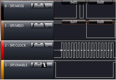
I have started to face issue with SPIA  RXBuffer on TMS28335 recently. TMS28335 is configured as SPI Master. I do see a valid response in the SPIRXBuffer from the Slave.

But when the RXBuffer is copied into a temporary local variable, this variable always remains 255.

However, the same code has been working for months on the older rev of board. The new rev board is giving this issue. Hardware seems to working fine as I see the data coming to the RX pin of SPI and a valid data into the RXBuffer.

What could be the issue?

PS: CCS v3.3, BIOS v 5.33.05, CGT 5.2.3 is used for both rev boards. The same code compiled with these versions work on old rev board and gives the above issue with new rev board. Hardware for new rev board been tested ok and SPi RXbuffer receiving valid data on new Rev board.


  • I am having a similar problem with the TMS320F28027.  My Piccolo card is set up as the master and I have an EEPROM set up as the slave. 

    I use the following function to do the SPI data I/O:

    Uint16 spia_putc(Uint16 data)

    {

        temp = data << (15-SpiaRegs.SPICCR.bit.SPICHAR);    //shift so that the correct number of bits is left justified                                            

        SpiaRegs.SPITXBUF = temp;                                                  //transmit the data

        while(SpiaRegs.SPISTS.bit.BUFFULL_FLAG == 1){}         //wait until the transmission is complete

        temp = SpiaRegs.SPIRXBUF;                                                       //get data from SPIRXBUF   

        return(temp);                                                                               //return the recieved data

    }

    I use this function as follows:

    ...

    spia_putc(READ_INSTRUCTION);

    spia_putc(ADDRESS);

    data_dump = spia_putc(DUMMY_SENT_TO_RECEIVE_DATA);

    //but I have to add the following to actually read the data

    data_actual = spia_putc(ANOTHER_DUMMY_SENT_TO_ACTUALLY_RECEIVE_DATA);

    ...

    I see the data transmit and receive correctly via a logic analyzer.  So I know it is there, but I am unable to read the data until I send a second dummy transmission on the SPI port.

    I have tried to add a wait for the INT_FLAG, but that just causes my read sequence to be canceled.  Also I have tried to read the SpiaRegs.SPIDAT register directly but get the same results as reading the SpiaRegs.SPIRXBUF

    I can account for this in software, but would like to reduce the overhead the SPI port takes.  (also it makes my code a lot less portable.)

    I am using CCS v4.2.2.00033 and the experimenters kit with F2802xx (Piccolo-A) Release 1.0 control card.


    any help would be greatly appreciated


    John

  • Hi, Mona

    Do you use XINTF?

    Did you relocate stack to external memory? Problems with XINTF interface might explain the behaviour you are observing.

    Where have you placed stack?

    Regards, Mitja

  • At the risk of hijacking this thread,  I will post a response.  (Not sure if Mona is still monitoring).

    (If in the future I see a post from Mona I will back off.)

    Thanks for your response.

    I can say that I do not know what the XINTF is.  And I couldn't find it in the Interrupts data sheet or the spi data sheet.

    Where would I find more info on XINTF?

    Also, I am using a chopped down version of the example that came with CCS V4.xx . 

    The specific example is Example_2802xSpi_FFDLB.c

    I have removed all the FIFO functionality and have the following setup for the Spi peripheral


        SpiaRegs.SPICTL.all  =  0x000E;                                        
        SpiaRegs.SPIBRR  =  0x000E;                                           
        SpiaRegs.SPICCR.all  =  0x0087;  
        SpiaRegs.SPIFFTX.bit.SPIFFENA = 0;     
        SpiaRegs.SPIPRI.bit.SOFT = 0;       
        SpiaRegs.SPIPRI.bit.FREE  =  1;       
        SpiaRegs.SPIPRI.bit.TRIWIRE =  0;      


    Other than those changes and the functions I created in my previous post I have not changed much from the original example file.

    So I have not touched the stack (and am a bit of a Noob so I don't know how to change the stack settings yet).


  • @John

    First of all I would say ignore the comments about XINTF.  For one thing, the 28027 has no XINTF, which is the external parallel interface.  I assume the reason Mitja asked is that if Mona has a stack in the XINTF, there may be timing issues with regards to local variables.  Nothing to do with the SPI itself.

    As for your issues.  After reading the F28027 SPI datasheet (http://focus.ti.com/lit/ug/sprug71b/sprug71b.pdf) I think I know what is causing your problems.  Basically it stems from the use of the check for BUFFULL.  This is a strange flag and I think you are slightly misunderstanding its use (I may be wrong, the wording is vague but i have seen similar flags).  To me, this flag represents the transferal of data from SPITXBUF to SPIDAT.  This occurs prior to transmission and thus does not indicate transmission actually has happened but can be confused for it.  I think its best summed up in a list of steps

    1) (No SPI for a while) BUFFULL = 0

    2) TXBUF written to by code -> BUFFULL = 1

    3) TXBUF -> SPIDAT -> BUFFULL = 0

    4) SPI transmission occurs.  During the transmission TXBUF written to by code -> BUFFULL = 1

    5) When transmission finishes: TXBUF -> SPIDAT -> BUFFULL = 0

    Basically after a long period of no SPI, you will need two checks of BUFFULL to ensure transmission is successful.  Which explains what you are getting.

    As far as a solution, this involves using interrupts or the interrupt flag.  The datasheet uses this code:

    SpiaRegs.SPITXBUF = data;
    while(SpiaRegs.SPISTS.bit.INT_FLAG !=1) {}
    data = SpiaRegs.SPIRXBUF;

    Now this is all well and good but you said that this "causes my read sequence to be canceled.".  What does this mean exactly?


    @Mona

    However, the same code has been working for months on the older rev of board. The new rev board is giving this issue. Hardware seems to working fine as I see the data coming to the RX pin of SPI and a valid data into the RXBuffer.

    What has changed HW and SW wise between the two boards?


    Hopefully this helps,


    Tim


  • According to the EEPROM that I use, when the Chip select line (inverted logic) gets raised (de-select the chip) it ends the read commands.  When I include the line:

    while(SpiaRegs.SPISTS.bit.INT_FLAG != 1){}

    instead of

    while(SpiaRegs.SPISTS.bit.BUFFULL_FLAG == 1){}

    I get the following wave form on the logic analyzer.


    This stops the command. (note during the second set of clocks the MISO line is high)


    This is what I get when I used, the code I attached.  (The wave form should look like this.)


    (note during the second set of clocks the MISO line is low;  this is what is expected)

    When I do the read of the SPIRXBUF, however, I get 0xFF.  In order to capture data from the line I need to send another character to the SPITXBUF before I can read the actuall data.

    After I dump that first character I can read data continuously, but I always have to dump the first value from the SPIRXBUF.

  • John,

    How are you driving the SPI enable line? And when?

    ----

    Also, the second picture shows me that the SPI is actually working perfectly.  During the first read of SPIRXBUF it gives 0xFF because that is what is on the line at the time of transmission.  The second read gives the appropriate data.  This is probably how the EEPROM chip itself works:

    1) Send command.  During the command being sent the MISO line is idle - Thus you should read 0xFF - it is what is on the line at the time of transmission

    2) Then for each dummy TX you get meaningful data back, as the EEPROM has fully received the command and has processed it.

    The BUFFULL approach seems to actually be working.

    Tim


  • Tim,

      I am allowing the SPI mechanism on the piccolo chip to drive the SPI enable line.  The chip takes the appropriate actions from what we set up in the spi control register (i.e. I have set up inverted logic for the SPISTEA pin) when I write to SPITXBUF.  At least that is what I assume, because that is what is happening :)  

    (I used to "manually" drive the SPISTEA pin but then, through trial and error, found out this wasn't really doing anything.)

      You are correct in saying that the second picture is showing the SPI working correctly.  And that is the nugget of my issue.  I see the SPI working with the logic analyzer, but when I read the SPIRXBUF after the second transmission I get a value of 0xFF, when I should be getting 0x00.  Reading the SPIRXBUF only returns the correct value after I write another character to the SPITXBUF.  (When reading a block of data every read after that is in sequence, but I always have to throw away the first byte of data.)

    I will go back and see if I can get the SPISTEA line to work manually for me.  Then perhaps I can try using the INT FLAG with better results.

    John


  • John,

    If you do the following you may get some results:

    1) CS -> low

    2) Write to tx

    3) Wait for int

    4) Read from rx

    5) Repeat 2-4

    6) CS -> high

    This should generally ensure that the CS pulse lasts the entire time.

    Tim

  • Hi John,

    I don't know how your SW works, but you might have issues if you are looking with CCS at SPIRXBUF instead of SPIRXEMU, as it will clear int flag, which might influence SW flow.

    just a thought.

    Mitja

  • Mitja,

      The data sheet says that SPIRXEMU is used for emulation purposes only.  I am not sure if this means it is unusable or there is some issues with it's use.

    Tim,

      I have been able to drive the CS pin manually.  This has cleared up my issue with checking for INT_FLAG.  What I noticed with this is that there must be an issue with the copy rate from the SpiaRegs.SPIDAT register to the SpiaRegs.SPIRXBUF.

    At any rate this cleared up not being able to read from the SPI port correctly. 

    The only downfall of this is that it effectively brings the data rate down to about 907k 800k baud for any read function, (which is down about 10%  20% from 1M baud that they claim).

    I wouldn't call this solved but I do have a work around for now.  I will keep working on a better set of code to remove the delays that I am seeing with the read functionality.  If/when I get to that point I will post my code to this thread.

    I appreciate all the help.

     John


  • As I stated in a previous post the BUFFULL method is always one read behind.  However it runs at near full speed because you are always keeping the TXBuffer loaded.

    I think your INT_FLAG is slower because you pause (TX-wait-RX-wait-TX-wait-RX) before you reload your TXBuffer.  In order to get the best of both worlds (it won't be 100% but hopefully close to it) I would recommend using interrupts.

    You need to set up two functions: TX and RX Interrupt

    In the TX function:

    SPI_TX(TXData[], Length)

     {

       TXPointer = TXData;

       TXLength = Length;

      Position = 0;

      CS low;

       SPITXBUF = *(TXPointer);

    }

    In RX Interrupt:

    SPI_RX_ISR

     {

        RXData[Position] = SPIRXBUF;

        if (Position < Length)

         {

            SPITXBUF = *(TXPointer+Position);

            Position++;

        }

     else

     {

       CS high;

    }


      Interrupt Code - See code examples

    }

    This means you call a function called SPI_TX, set up a TXBuffer - you may need to fill this with dummy writes for reads. The SPI will keep writing from the buffer until its done. This should hopefully get your SPI going at near full speed (SPITXBUF is not loaded for only a few cycles).


    Tim


  • Tim,

      Thanks for the help.  I will implement it with the interrupt.  I appreciate you taking time to explain it to me!!!

    John

  • Hello John,

    I know its an old post, but maybe you read this.

    You said you were able to manually drive the CS pin. Could you please past your solution for that ?


    Thanks !

  • //I am assuming you are using the SPI-A module

    //pin setup

    GpioCtrlRegs.GPAMUX2.bit.GPIO16 = 0x01;  //set pin to be SPISIMOA

    GpioCtrlRegs.GPAMUX2.bit.GPIO17 = 0x01;  //set pin to be SPISOMIA

    GpioCtrlRegs.GPAMUX2.bit.GPIO18 = 0x01;  //set pin to be SPICKLA

    GpioCtrlRegs.GPAMUX2.bit.GPIO19 = 0x00;  //set pin to be GPIO (but will really be used as SPISTEA)

    //I use these #defs to make things more clear later

    #define ASRT  GpioDataRegs.GPACLEAR.bit.GPIO19 = 1;  //enable the chip select pin

    #define DASRT  GpioDataRegs.GPASET.bit.GPIO19 = 1;  //disable the chip select pin

    //note here you would setup the rest of your registers to run SPI-A, clocks and SPI regs ...

    //this is a utility function for sending a chunk of data

    Uint16 spi_transceive(Uint16 data)

    {

      while(SpiaRegs.SPISTS.bit.BUFFULL_FLAG == 1){}

      SpiaRegs.SPITXBUF = (data << (15 - SpiaRegs.SPICCR.bit.SPICHAR));

      while(SpiaRegs.SPISTS.bit.INT_FLAG == 0){}

      return(SpiaRegs.SPIRXBUF);

    }

    //  this is a function that uses the spi_transceive.  i.e. to read from ROM/RAM

    Uint16 do_stuff(void)

    {

      Uint 16 data = 0;

      ASRT;

      spi_transceive(read_instruction);

      spi_transceive(address);

      data = spi_transceive(dummy_transmission);

      DASRT;

      return (data);

    }