Because of the holidays, TI E2E™ design support forum responses will be delayed from Dec. 25 through Jan. 2. Thank you for your patience.

This thread has been locked.

If you have a related question, please click the "Ask a related question" button in the top right corner. The newly created question will be automatically linked to this question.

DRV8312-69M-KIT EVALUATION PROBLEM

Other Parts Discussed in Thread: DRV8312, TMS320F28069, MOTORWARE

Hi,

I am trying to evaluate DRV8312-69M-KIT RevD. I follow the guidelines given in the Quick start guide (version 1.0.4) for Evaluating InstaSPIN-MOTION (F2806xM) Using Graphical User Interface.

I check all the connections, toggle switch positions and switch positions according to the guidelines. I connect the power adapter. I first plug the USB connection cable to the computer, then to the control board. The computer recognizes the control board. Until here everything is fine.

The problems:

1-When I launch InstaSPIN_MOTION_F2806xM.exe, it usually takes a long time for the board to be initialized. But, on the sorftware side (interface), I get no faults. 

2-The fault lights on the control board, on the other hand, turn RED. According to the Quick Start Guide, I am supposed to  RESET this fault by using RSTA by putting it at RESET and then back at MCU position. I do this, but the fault is NOT cleared. 

Any help is appreciated.

-Sertug

  • Mehmet,
    Is this still an open issue? The board should not fault when you start-up the GUI and you should not need to toggle the reset switches.

    I would check the jumpers and settings on the EVM, make sure the motor is wired in correctly (or first try without any motor attached), and possibly reinstall the GUI.
  •   Hi Chris,

    Yes, the issue is still open. I already tried with a fresh installation of the GUI: no-go. I tried without any motor: no-go

    According to the Quick Start Guide this is the configuration I need to have on the board:

    JP1: VR1-Middle

    JP2: Populated

    M1:High-Middle

    All three toggle switches are in MCU position

    Motor Wires to MOA, MOB, MOC

    DC voltage to J9 or PVDDIN

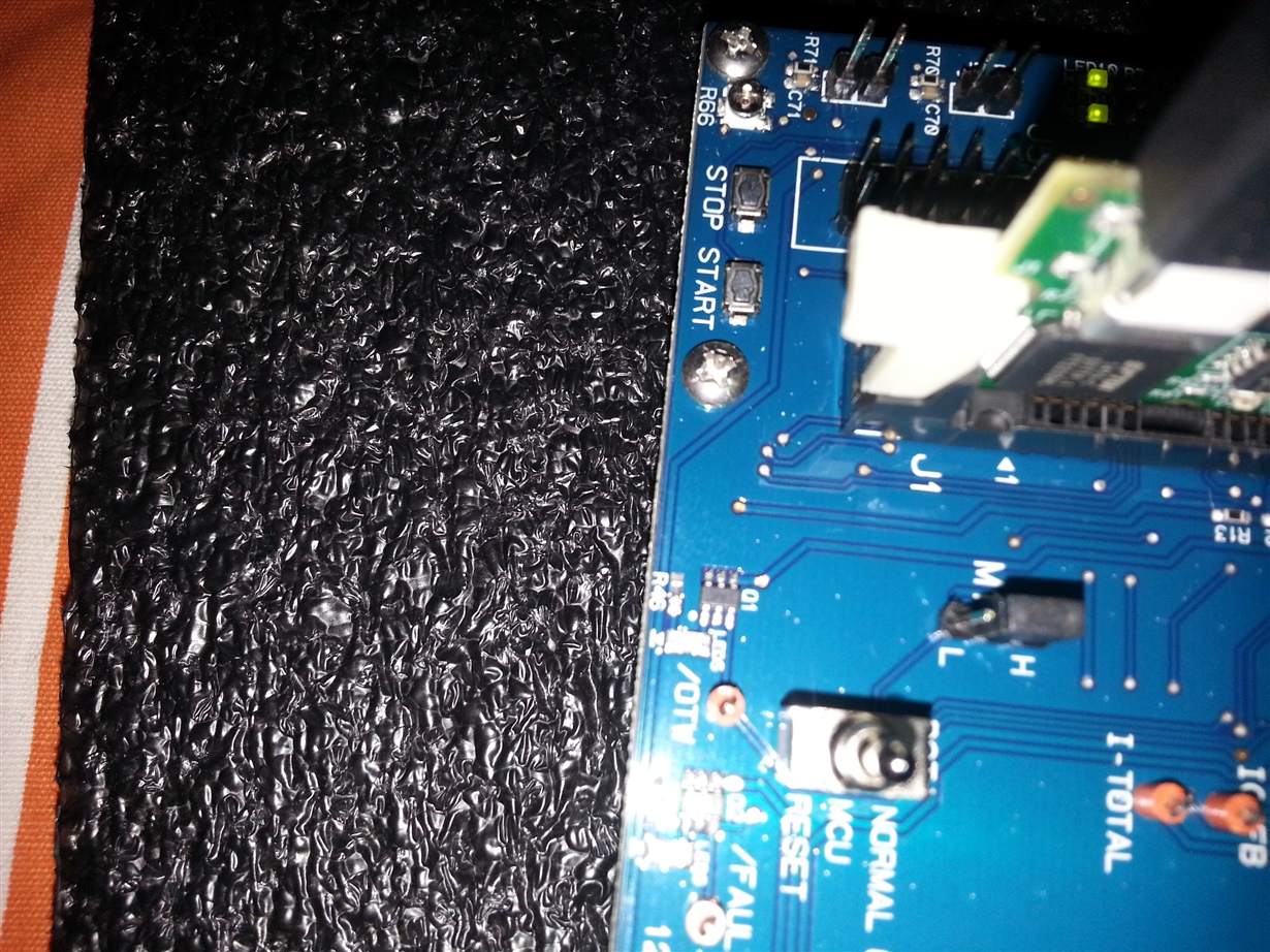
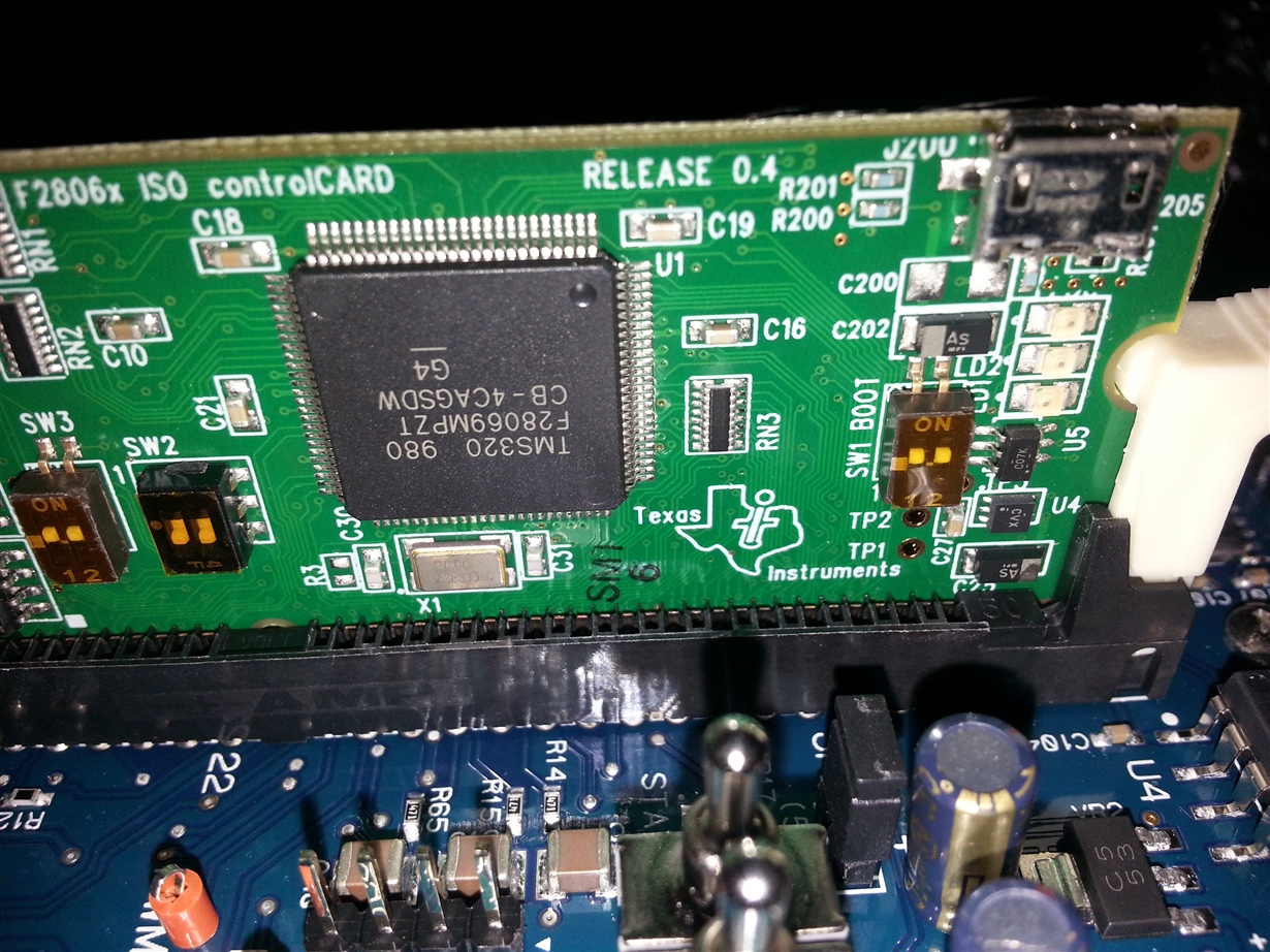
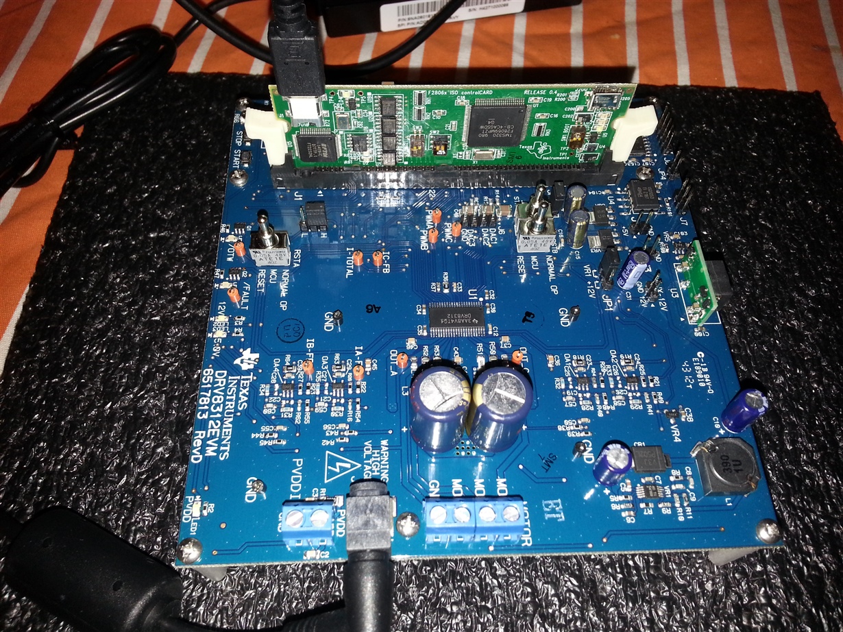
    and these are the snapshots from my board:

  • settings are correct

    when you power the DRV8312 board it immediately faults? or when exactly?

    I'm forwarding to the DRV8312 team to see if they have ideas...I'm leaning towards a damaged EVM.
  • Hi Mehet,

    Can you check the nFAULT and nOTW pins? It would also be good to understand when exactly the error occurs, when motor enables, on power application, etc.

    There is table on page 11 of the datasheet to decode the exact fault from the motor driver.

  • Hi Chris,

    The fault lights on the Control Card (2 RED lights) turn on when I execute the InstaSPIN_MOTION_F2806xM.exe (it is fine when it says it is connectiing to the device. The fault occurs after it says loading the application)...

  • have you tried uninstalling then reinstalling the GUI?
  • Hi again Chris,

    Yes, I have tried to uninstall and re-install the GUI. That did not work either, like I mentioned before.

    I do not think it is a hardware problem. When I follow the instructions in InstaSPIN Projects and Labs User’s Guide for Lab 2a exercise: Using InstaSPIN for the First Time out of ROM, the board functions just fine and I am able to get the estimated motor parameters.

    The problems appears whenever I try to use the GUIs (any of them). I update the user.h file as instructed by using the estimated values from Lab2a exercise. I, then, do the following,

    1-Launch Code Composer Studio v6.1.2

    2-Go to target configurations->Projects->proj_lab02a->TMS320F28069_xds100v2

    3-Right click on the target configuration and Launch Selected Configuration

    4-Click on Run, Connect Target (it connects succesfully)

    5-Go to Run->Load

    6-Go to C:\ti\motorware\motorware_1_01_00_15\sw\solutions\instaspin_foc\boards\drv8312kit_revD\f28x\f2806xF\projects\ccs5\proj_lab02a\Release and choose proj_lab02a.out 

    7-Terminate and close CCS

    8-Unplug the power and USB. Then power the board back up and insert the USB cable to the control board. I see the RED LED blinking (as it is supposed to). 

    9-Place the proj_lab02a.out file in the C:\ti\guicomposer\webapps\InstaSPIN_FOC_F2806xM location and launch InstaSPIN_FOC_F2806xM.exe

    10-During the inialization process, when the application is being loaded onto the board, 2 LEDs on the control card light up. 

    When I try the same but with the universal gui, I am able to lauch the GUI without any fault LEDs on, but all the variables in the GUI have a red cross next to them (they are not defined). 

    I assume I must be doing something wrong...

  • if you are trying to use this GUI
    C:\ti\guicomposer\webapps\InstaSPIN_FOC_F2806xM

    you should NOT change the appProgram.out file. We only support the appProgram.out which is included with the original installation.

    if you want to use the UNIVERSAL GUI
    C:\ti\guicomposer\webapps\InstaSPIN_F2806xM_UNIVERSAL
    you can copy proj_lab02a.out to this location and RENAME appProgram.out
    Then simply run the .exe
    you do NOT need to load proj_lab02a.out onto the target using CCS. The GUI .exe does this for you.


    Lastly, these two GUIs can NOT be installed at the same time. Whichever one was installed most recently will take precedence and the other will not work correctly.

    I recommend uninstalling both, and then just reinstalling one for further testing.
  • Thank you for your help.

    1-I uninstalled both GUIs, re-installed INSTASPIN_FOC and INSTASPIN_MOTION using GUI_Composer_InstaSPINs_F2806xM_install.exe
    2-I tried using C:\ti\guicomposer\webapps\InstaSPIN_FOC_F2806xM without changing the appProgram.out file.
    3-I get the fault LEDs again while loading and it takes forever to load.

    It is the same with C:\ti\guicomposer\webapps\InstaSPIN_MOTION_F2806xM

    4-I try out the C:\ti\guicomposer\webapps\InstaSPIN_F2806xM_UNIVERSAL following the steps as you instructed and it works just fine. I am able to identify the machine parameters and run the machine (proj_lab2a).
    5-There I face another problem. After trying proj_lab2a I would like to proceed by trying other projects. Unfortunately, except for proj_lab2a and proj_lab2b all the other projects do not have the .out file in their relative Release folders (those folders are empty).

    Please help me out with these two problems.
  • regarding 1-3 I think this is something that has corrupted the installation. if you really want to get this working try installing in a different path, like C:\ti_2\guicomposer

    regarding 5
    you need to import and build the proj_lab## in CCS. Once successfully built you will find a RELEASE or FLASH folder where expected with the corresponding proj_lab##.out
  • regarding 1-3: I tried and it does not help.
    regarding 5: Perfect, thank you.