This thread has been locked.

If you have a related question, please click the "Ask a related question" button in the top right corner. The newly created question will be automatically linked to this question.

DAC7760 (Eval-Board) interfacing with TMS320F28377D (EVAL-BOARD),trying to communicate with SPI.

Other Parts Discussed in Thread: DAC7760

Hello, 

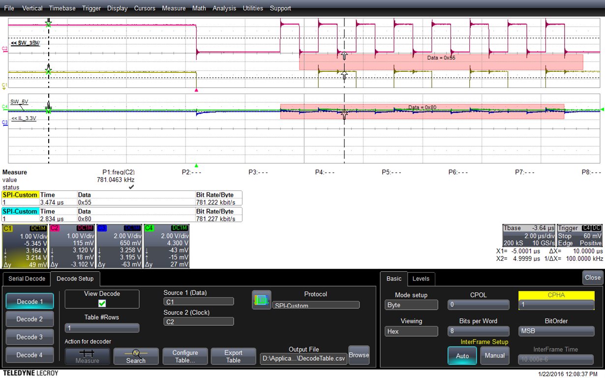
I have attached below the waveform capture of the SPI bus.

I am not able to LATCH (rising edge of the Latch signal) exactly at the LSB of the Data.  

Tried using TX-FIFO interrupts, to get an interrupt after I send 24 bits of data so that I rise the LATCH, but the interrupt is not working fine.

Could you please suggest any other way to synchronize and Latch the data at LSB.

Thanks ,

Prashanth

  • Prashanth,

    I need a little more information in order to help you out.

    1. is F2837x SPI the Master or Slave?

    2. Can you label the Signals on the Screenshot? Yellow is input or output data from the Spi? what does the Green Signal correspond to?

    3. What are your FIFO settings? (when will the TX FF interrupt be triggered? how about the RX FF interrupt?

    4. When does the latch signal need to be triggered?

    The above questions should help me understand what you are trying to accomplish.

    Thanks,

    Mark

  • Thanks for the reply Mark !
    F2837D is the Master .
    Yellow is the MOSI signal (signal out from the Master-F28377D).


    SpiaRegs.SPICCR.bit.SPISWRESET=0; // DISable SPI
    // SpiaRegs.SPIFFTX.bit.SPIRST = 0;
    // SpiaRegs.SPIFFTX.bit.TXFIFO=0;
    SpiaRegs.SPICCR.all = 0x0007; //7 //0x000F is for Reset on, rising edge, 16-bit char bits
    SpiaRegs.SPICTL.all =0x0006; // Enable master mode, normal phase, TALK enabled
    SpiaRegs.SPISTS.all=0x0000; // enable talk, and SPI int disabled.
    SpiaRegs.SPIBRR.all =0x003F; //3f //SPI baud rate = LSPCL/128
    // SpiaRegs.SPICCR.all =0x0087; //before 9F // Relinquish SPI from Reset
    // SpiaRegs.SPIPRI.bit.FREE = 1; // Set so breakpoints don't disturb xmission
    //SpiaRegs.SPIPRI.bit.SOFT = 1;
    // Initialize SPI FIFO registers
    // SpiaRegs.SPISTS.bit.OVERRUN_FLAG =1; // Not to USE when FIFO are enbled
    // SpiaRegs.SPIFFTX.bit.SPIFFENA = 1;//SpiaRegs.SPIFFTX.all=0xC062; //0xC060; //0xE040;
    SpiaRegs.SPIFFTX.bit.TXFFINTCLR = 1;
    SpiaRegs.SPIFFRX.bit.RXFFOVFCLR= 1;//SpiaRegs.SPIFFRX.all=0x0021; //0x2044;
    SpiaRegs.SPIFFRX.bit.RXFFINTCLR= 1;
    SpiaRegs.SPIFFTX.bit.TXFIFO=1;
    SpiaRegs.SPIFFRX.bit.RXFIFORESET=1;
    SpiaRegs.SPIFFTX.bit.SPIRST = 1;
    // SpiaRegs.SPIFFTX.bit.TXFFIL = 8;
    // SpiaRegs.SPIFFRX.bit.RXFFIL = 1;
    // SpiaRegs.SPIFFTX.bit.TXFFIENA = 0;
    // SpiaRegs.SPIFFRX.bit.RXFFIENA = 0;
    SpiaRegs.SPIFFCT.all=0x0; //next word in TX FIFO buffer is transferred to SPITXBUF immediately upon completion of transmission of theprevious word.

    SpiaRegs.SPICCR.bit.SPISWRESET=1; // Enable SPI
    // SpiaRegs.SPIFFTX.bit.TXFFINTCLR = 1;
    // SpiaRegs.SPIPRI.bit.FREE = 1;


    The Latch need to be triggered after I send 24 bits (3x8-bit Transmissions) on the MOSI line. I am trying to interface with the TI DAC module (DAC7760).
    Right now I am trying out with transmitter side.


    I need your guidance.
    Thanks
    Prashanth
  • Green Signal is the Latch !
  • Prashanth,

    Try setting it up using the Receive FIFO interrupt instead. This will be triggered when the third word has been fully received. Even though you are not reading or care about any data, you can toggle your latch signal inside of this interrupt.

    -Mark
  • Thanks Mark !
    Instead of TX FIFO-INT you are suggesting to make use of RX FIFO-INT after receiving 24 bits ,sure will try it out !

    -Prashanth
  • Hi Mark,
    I have another doubt, even if I write to the CPOL (Clock polarity bit) and CPHA ( Clock Phase bit) in the register as zeros.
    There is a shift when I see it on the scope and the data will be valid for CPHA =1.
    I thought of sharing the scope picture but could not attach it here ( Where else can I share the scope picture) .


    Thanks
    Prashanth
  • I could attach those captures too.

    Thanks 

    Prashanth

  • The Red signal is the SCLK.

    Yellow is the MOSI (Data out from F28377D).
    In the first capture, even in my code CPOL & CPHA are zeros, but on the scope I need to change CPHA = 1 to get a valid data on MOSI.
    In the Second capture,even in my code CPOL = 0& CPHA = 1, but on the scope I need to change CPHA = 0 to get a valid data on MOSI.

    I am not able to understand why is this random behavior happening.


    Thank You so much Sir !
    Prashanth
  • Prashanth,

    The data is correctly coming from SIMO in both cases.
    0x55 = 0101 0101.

    In the first capture, the data is changed at each rising edge of the clock signal.
    In the second capture, the data is changed one half cycle before the first rising edge of the clock.

    I think you may have misunderstood the clocking schemes. Refer to Figure 18-7. SPICLK Signal Options of the TRM. this accurately gives a representation of the different polarity and phase alignments with respect to the transmit and receive latch points.

    -Mark
  • Ok, I was thinking the data change should happen from the 1st  SCLK cycle itself. If you see in the 1st capture,  the data is changing   at each rising edge of the clock signal and In the second capture, the data is changed one half cycle before the first rising edge of the clock. BUT NOT FROM THE 1st  SCLK CYCLE. 

    I think, I misunderstood that.

    I am trying to implement TX-FIFO interrupt , but as soon as I initialize SpiaRegs.SPIFFTX.bit.SPIFFENA = 1, the TXFFINT is always high  even after clearing the interrupt (SpiaRegs.SPIFFTX.bit.TXFFINTCLR = 1;).

    I need your advice. 

    Thank You Sir,

    Prashanth

  • Prashanth,

    This behavior is expected. If there is nothing in the TXFIFO when the interrupt is enabled, The interrupt will fire.

    I would recommend that you do not enable the TX FIFO until you are prepared to transmit data. You can disable the interrupt when the burst is complete.

    If you want full control over when you transmit and receive, you could also decide to not use the transmit interrupt.

    Thanks,
    Mark
  • Thanks Mark !

    I am  trying to use  SPINT (instead of TX-FIFO interrupt) , I need an interrupt only for transmission.  

    Trying to load the data to the TX-BUF  in the ISR. 

    But when I try to increase the SPICLK to 10 MHZ , i do not see any transmission even when I give full-200MHZ to the SPI module, i.e. by

     LOSPCP.bit.LSPCLKDIV = 0. 


    As an example, my goal is to have the SPICLK at 10 MHZ and try to load the data to TX-BUF at 16khz .

    Thanks a lot, need your  advice.

    -Prashanth 


  • Prashanth,

    So the SPI is no longer able to transmit anything? Please verify that you have not accidentally left the module in reset.

    -Mark