This thread has been locked.

If you have a related question, please click the "Ask a related question" button in the top right corner. The newly created question will be automatically linked to this question.

[FAQ] Sticky: MathWorks Solutions for C2000 MCU’s

Other Parts Discussed in Thread: TMS320F28335, CONTROLSUITE, TMS320F28035, TMDSDOCK28379D, LAUNCHXL-F28379D, TMS320F28379D, TMS320F28379S

Save design time and get into production faster with C2000 MCU’s with MathWorks solutions.

To begin you use MATLAB® and Simulink® to create and simulate your algorithms. Next you use Embedded Coder® to generate production code of your algorithms. Embedded Coder support for Texas Instruments C2000 includes:

        • Automated build and execution
        • Block libraries for on-chip and on-board peripherals such as ADC, digital I/O, ePWM, SPI, I2C, and more
        • Real-time parameter tuning and logging using external mode
        • Processor optimized code including DMC and IQMath libraries
        • Ability to perform processor-in-the-loop (PIL) tests with execution profiling
        • Examples for motor control and power conversion that run on TI C2000 hardware

You can also generate code that runs on the Control Law Accelerator (CLA), a co-processor available on select TI Delfino and Piccolo processors.

For multicore systems, you can use SoC Blockset with C2000 Support for SoC Blockset to build your system architecture using processor, inter-processor communication, interrupt and I/O models, and simulate the architecture together with the algorithms. This allows you to partition algorithms between multiple cores to achieve design modularity and improve performance, and to account for issues like ADC-PWM synchronization and latency.


From within MATLAB you can access hardware support for Embedded Coder via the Add-On Explorer from the MATLAB toolstrip.


Search for C2000, and select to download and install free C2000 library blocks. You insert and configure the blocks, which include IO and various functions, in your Simulink model. Then you use Embedded Coder to generate production code of your algorithm and run it directly on your TI C2000 MCU. The library blocks include documentation, example models, and support C2000 Piccolo, Delfino, and Concerto families.


Note: Using Embedded Coder requires additional MathWorks software: MATLAB®, Simulink®, MATLAB Coder™, and Simulink Coder™.

You can also just generate production code of your algorithms which can be imported and integrated into an existing Code Composer Studio project.

--- ---

Here is more info including how-to videos and examples you can run with TI hardware kits:


    • Details and Examples:

      • C2000 Hardware Support webpages:

      • Delfino: F2833x, F2837xS, F2837xD, C2834x

      • Piccolo: F2802x, F2803x, F2805x, F2806x, F2807x, F28004x

      • Concerto: F28M35x, F28M36x (C28x + ARM Cortex M3)

      • Legacy: C280x, C281x, C2833x, F281x, F280x

      • C2000-Based Examples


Content Updated 2020-11-02

  • Hello,

    I am using the F28379D with Simulink and it worked fine so fare (toggling LED, output PWM, reading ADC).
    However I am having some trouble with the CAN functionality.

    I would like to periodically (let's say at 10 Hz and 20 Hz) transmit CAN messages with different ID's.

    However the message with the highest priority simply spams the CAN-bus and no other message is transmitted.

    For my example code I used two timers to generate periodic interrupts.
    Using the hardware interrupt I call two function-call subsystems periodically. (This works fine as I employ two blinking LEDs to verify the periodic calls to the subsystems.)
    Each of the subsystems should transmit a CAN message with a different ID.
    But only the message with the higher ID/priority is transmitted and this at a much higher frequency than the LED blinking.

    As far as I understand the problem, the CAN message is not posted, transmitted once and then the transmission is stopped. But the message simply remains in the message box and is therefore posted every-time the CAN-bus is free.

    Enabling blocking mode did not change the behavior.

    Do I need to somehow use the "Interrupt after transmission" to change the ID of the message to a lower priority in order to allow other messages to pass. I doubt that this is the intended behavior of the eCAN transmit block.

    Best Regards,
    Bob
  • Bob,

                A message in a mailbox is transmitted only when the TRS bit of that mailbox is set. I presume your timer ISR sets the TRS bit. Therefore you see that message over and over again on the bus. Since this timer interrupt occurs at a more frequent rate than the other timer, messages from this MSGID "monopolize" the bus and does not let the other message get through. Perhaps you could have a software flag called "New_data". You set this flag when you have new data to transmit and clear this flag once the transmission is done. Your ISR should check this flag and initiate a transmit only when this  flag is 1. To summarize, there is nothing abnormal with the behavior of the CAN module. The device is doing exactly what you are asking it to do.

  • Dear Hareesh,
    thank you for your response. If I would be writing C-Code I would agree with you.
    However I am planning on reducing the need of manually written C-Code to the absolute minimum in my current project and instead rely on Simulink code only.
    I am using the Matlab/Simulink target support package of the C2000. And in there is the "eCan Transmit" block, which I use to transmit the CAN messages. The current behavior of the CAN module is probably due to the way this transmit block is implemented, (which I do not intend to modify).

    Would it be possible to propose a solution relying only on the currently implemented library blocks?

    Best regards
    Bob
  • Bob,

    This is the natural behavior of CAN transceivers, they keep sending the last message stored in their buffer unless a new message comes in. The MCU laso sends the higher priority message first but if you set up your Simulink model correctly, I don't think you get the issue. Here is how I constructed my model in Simulink:

    Inside the subsystem:

    So as you can see I'm toggling two LEDs with 1 and 2 sec delay interval to make sure my subsystem is getting triggered, and transmitting two different messages over CAN with two different ID and Mailbox priorities as below:

    1. Send "1" and increment it by 1 every 2 sec. MSGID: "111000111" (1C7) and Mailbox number: 2

    2. Send "1" and increment it by 1 every 1 sec. MSGID: "111100111" (1E7) and Mailbox number: 3

    Here is the result on CANalyzer:

    As it's clear, both messages are being transmitted and their value is getting incremented. 

    Hope it helps you to find the issue in your model,

    --Kash

    If my post answers your question, please click on "Verified answer".

  • Bob,

    The default blocks in the C2000 library don't transmit continually, at least not in my implementation.

    I suspect you are missing the ack bit, which can cause the transmitting node to continually attempt to resend the frame.

    From http://www.ti.com/lit/an/slla109/slla109.pdf

    ===============

    Finally, an acknowledgement (ACK) error occurs when SLLA109 4 A System Evaluation of CAN Transceivers the transmitter does not monitor a dominant bit in the ACK slot to signify that the message has been received properly by another node.

    also:

    In a two-node experiment, if one node enters the bus-off state, the bus would become silent, or the other node would continue to retransmit until the reception of a proper ACK bit. Either case represents experimental conditions, causing a heavily disturbed bus that is not recommended for use in a final application.

    ===============

    What tool are you using to monitor the bus? If you are using a scope it will (in my experience) not send an ack bit. I think most monitor tools (CANalyzer etc.) will send the ack bit by default. Do you have another node on the bus? If not you will be missing the ack bit and in my past experience this can cause the transmitting node to continually attempt re-transmit. I saw this when using a scope to monitor a CAN bus and I needed to add a second node to stop the re-transmit.

    The F28379D has two CAN busses. You could try connecting them together so the second one could be the "receiving" node and send the ack bit. I assume you are using a CAN transciever(s) and not simply looking at the Tx & Rx from the micro.

    Good luck,

    Don

  • Dear Don,

    I am indeed using a scope (with CAN decoding functionality) to monitor the bus, but I am pretty sure that this one does not send any ack bit.
    And as I was testing it as a single node setup, the described behavior of "the transmitting node to continually attempt to resend the frame" sounds like a plausible explanation.

    I am using the F28379D Launchpad development kit, which has only a single CAN transceiver on it. But I will simply connect two of the kits in order to test the hypothesis. Otherwise I might also find a CANanalyser somewhere in the lab.

    Thank you all for being so responsive!

    Update:

    Problem solved. With two nodes on the CAN bus the problem no longer appears. So I was indeed missing the ack bit.

    I will be more careful with the correct "electrical" setup of the CAN bus for the final application.

    Thank you for your help.

  • Hi all,

    I have a question about using Mailboxes to transmit and receive CAN messages in Simulink. As far as I know I'm limited with 32 Mailboxes for CAN communication in Simulink. This means I can have up to 32 distinct CAN messages. I'm wondering if there is any way in Simulink to use the same Mailbox for multiple messages so I would be able to have more than 32 messages.

    Based on TI expert, I can use Masking feature in CCS to use the same Mailbox for multiple messages. Can i use Masking feature in Simulink? if so, how do I use it?

    I was thinking of making a library that contains eCAN_TX/eCAN_RX block and call it in my model when I'm ready for transmission.

    Thanks,

    --Kash

  • Hi Kash,

    I received an example of how to workaround this from my development team, but I cannot attach in E2e (file extension is not allowed). Here are their comments and a screenshot

    In this example we are configuring the mask settings for mailbox – 0 to receive any message with standard identifier less than 256.

    This mask configuration is done in the system initialize block as we don’t have a Simulink block to do the same. Thus with the mask settings, we can receive more than one message per mailbox thus overcoming the restriction of receiving only 32 distinct message.


    DM me your email address and I can send file to you.

    -Brian

  • Kash,

    Trying to add attachment here as .zip.  Ugly URL, so please let me know if it works correctly.

    /cfs-file/__key/communityserver-discussions-components-files/171/CAN_5F00_Tx_5F00_multi_5F00_ID_5F00_r2014b.zip

    -Brian

  • Hi Brian,

    Thank you very much for your support.

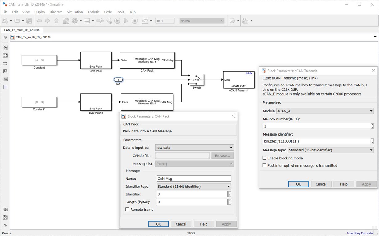
    That's funny but I solved it yesterday by myself and surprisingly my solution is exactly the same as your development teams :))), take a look at the below model, I toggle between two message every 1 sec:

    I tested several approaches but it seems to be the only way to transmit several message with one Mailbox. I'm glad that my method is already approved by Mathwork development team. :) 

    Regards,

    --Kash

  • Great Work, Kash!
  • Thank you Guatam,
  • Hi Brian
    I am using ADC block for TMS320F28335 C2000 MCU in Embedded Coder. Is the output of this block in SIMULINK (i.e. the value fed to the input of the next connected block in Simulink ) in the form of :

    0-3 [corresponding to 0-3V range supported by ADC], or
    0-4095 [corresponding to 12 bit ADC output], or
    0-65535 [corresponding to 16 bit ADC Result Register]

    I need to perform some operation on the variable measured by the ADC Block. Thus , the above information is very important for me.
    Also, is there a way i can monitor the real time measured ADC values within SIMULNK itself?
    I appreciate you taking out time to respond to my queries. I shall be grateful. Thank You!
  • Bilal,

    The ADC output values for TMS320F28335 are in the range 0 to 4095 because the ADS is 12-bit converter for c2833x MCUs.

    For c2837xD MCUs, you can choose between 12-bit single-ended input or 16-bit differential inputs.  In 16-bit mode, the input voltage is sampled through a pair of input pins which means the differential inputs between the two channels is measured.

    --Kash

    If my post answered your question, please click on "Verified Answer" button. 

  • Hi Bilal,

    I don't exactly understand your question. The doc page for the F28335 ADC block is here: https://www.mathworks.com/help/supportpkg/texasinstrumentsc2000/ug/c280xc2833xadc.html

    The doc specifically says: 

    The output of the ADC is a vector of uint16 values. The output values are in the range 0 to 4095 because the ADC is 12-bit converter.

    ---

    If this doesn't answer your question, please feel free to contact MathWorks Technical Support.

    -Brian

  • Khashayar,

    Please clarify whether the output of ADC Block within SIMULINK is 0-4095 or 0-3.
    For example, the ADC input of TMS320F28335 can vary from 0-3 Volts. I want to measure the voltage at the input of ADC, and apply logic that my program is triggered only when input voltage is greater than 1Volt. So, in SIMULINK model do i need to compare output of ADC Block with constant 1 or with constant (4095/3) ?

    Bilal
  • Thank You Brian ! Is the ADC Support Document only for MATLAB 2017a ? Is it valid for earlier releases also? I am using MATLAB 2012a.
  • Bilal,

    We have archived doc of older versions of our software. Here is the link for R2012a (login required): www.mathworks.com/.../c280xc28x3xadc.html

    -Brian
  • Bilal,

    The outputs range 0 to 4095 because the ADS is 12-bit converter. If you want to read 1v, you need to use a "compare to constant" block equals to 4096/3.

    --Kash

    If my post answered your question, please click on "Verified Answer" button. 

  • Hello,

    I am currently working on a robotic wheeled prototype. I am therefore using the TI Launchpad as microcontroller and I use the Embedded Coder of Simulink to program. As I have two main (computationally heavy) tasks which can run independently up to a certain degree, I was planning to make use of the two cores of the TI Launchpad.
    The current state is that I managed to let the two tasks run simultaneously successfully. I am currently stuck at the important point of the project that the two processes (cores) can transmit data between each other. It is not necessary that one process stops and waits for the data of the other but only that they have a shared registry out of which the one process reads the data when needed and the other process updates the data when ready.
    As this point is crucial for the prototype, it would be very nice if someone could provide me with an exemplum how to do this, or if this is not possible if there are any hacks that could work.

    Thanks,

    Marc
  • Hi Marc,

    I am investigating and will post a response when I get feedback from my colleagues.

    Thanks,

    -Brian

    PS: For faster response, you can always contact MathWorks Tech Support. Our Tech Support is truly excellent - nearly everyone there has a MSci/ PhD in Engineering or CompSci.

  • Hi Marc,

    I heard back from the devel team. Here is their feedback / suggestions:

    ---

    For more information on data exchange between the 2 CPU cores, refer the F28379D device data sheet (Technical Reference Manual) that is shipped with TI Control Suite.


    Please note: Out of reset the CPU1 is master and is responsible for configuration of peripherals. However we can have configurations done in such a way that even CPU2 can trigger a given peripheral operation. For Example ADC - SOC trigger can be configured between CPU1 or CPU2 as well and Result Register can be read from either of the cores independently. The same is with CAN, the MailBox are Read/Write from either core. This is with respect to peripherals.
     
    If you want to exchange data between cores then the Shared Global RAM is handy. Mem Copy block can be deployed to do this job.
    You need to use IPC Module to synchronize the data movement between the cores.


    Thus you will have to focus on the following IPC features:

    • Message RAMs

    • IPC flags and interrupts

    • IPC command registers

    Feature wise they are independent of each other but can also be combined based on application needs.

    More information on IPC and it configuration is again found in F28379D device (Technical Reference Manual).


    ---


    HTH,

    -Brian


    PS: I am travelling next week and wont be active on the E2E forums - please contact MathWorks Tech Support if you need additional assistance.

  • Hi Brian,

    Need to work on f28379d , Any idea the support package is available in matlab R2017a??
    If possible please provide me the list of tools I required to work on f28379d bootloader.

    Thanks
  • ashok kumar6 said:
    Need to work on f28379d , Any idea the support package is available in matlab R2017a??

    The controller was supported in 2016b itself. Have a look at this video:

  • Ashok,

    Matlab 2017a supports F28379D, check this link out:

    This new version even provides you with the C code when you build!

    Good luck!

    --Kash

    If my post answered your question, please click on "Verified answer" button.

  • Hi Khashayar olia,

    Thanks for you are reply.

    The C code can be generated for CCSv7 also??
    In one of the post in the above link mentioned C code will be generated for CCSV6 and v5.

    Thanks
  • Ashok,
    I haven't tried with CCS v7, will update you later.

    --Kash
  • Hi Ashok,

    CCSv7 is not yet officially supported by MathWorks - we're actively working on it, and hopefully it will be ready soon. For best results (today) use CCSv6.

    -Brian
  • Is it possible to access the registers in Simulink environment? for example access to "MSGID" for CAN communication or "SCICCR" for SCI communication? if so, is it possible to read and write them throughout the software?

    Thanks,

    --Kash

  • Hi Kash,

    Here's the info I have from my development team: 

    Yes, it is possible to be able to access individual registers using the memcopy block. Attached is a model that demonstrates the same, but not necessarily for the mentioned registers. The same can be extended for any memory mapped registers.

    Open the model->go to subsystem “FOC Algorithm Motor 2”-> double click one of the “Memory Copy” block. Under Source code symbol: we have actually specified the register details from where we intend to read.

    Example model is here:

    /cfs-file/__key/communityserver-discussions-components-files/171/c28379Dpmsmfocdual_5F00_ert_5F00_cpu2_5F00_17a.zip

    HTH,

    -Brian

  • Hi Brian,

    The embedded coder Addon package tail/free support for C2000 mcu is available, please confirm.
    Am using the R2017a trail version, tried to install the C2000 mcu, but it has trown error need to install the Embedded coder, which I am not able to install.

    Thanks
  • Hi Ashok,

    The MathWorks C2000 Support Package is a free download, but it does require Embedded Coder. It wont work or install without it. If you have a trial license, contact the sales rep that set up your trial and have them add the code generation products to your trial. You will need MATLAB Coder, Simulink Coder and Embedded Coder. Note: You cannot self-trial the code generation products at this time - you have to consult with your local MathWorks office (or Distributor) to get these products added to a trial.

    -Brian
  • Brian,
    Thanks for your help but I wasn't able to open it up since I'm using 2016b version. Is it possible to convert it down to lower versions?

    Thanks,
  • Hi Kash,

    Try this one - It's been saved in R2016b. Note that F28379  isn't "officially" supported in 16b, but the model should open and will probably work, we just didn't have F28379 in the drop down as that chip was launched after R2016b was published.

    /cfs-file/__key/communityserver-discussions-components-files/171/c28379Dpmsmfocdual_5F00_ert_5F00_cpu2_5F00_16b.zip

    Cheers,

    -Brian

  • Thanks for your help.

    But F28379D is supported in 2016b, as you've told me couple of months ago. I've done lots of test through 2016b and it does have F28379D in the drop down:

    --Kash

  • Hi Kash,

    True. Except the initial release of our C2000 Support Package for R2016b (September 2016) did NOT include the F28379 in the drop down. We updated the support package to add it after the release. If you ever see "Update" in your Add On-Explorer or Add-On Manager, go ahead and make that update - as we've probably done some sort of bug fix and re-released the Support Package.  

    -Brian

  • Brian,
    Thanks for your confirmation.

    Regards,
  • How do i get the I2C blocks to do the following sequence?

    1. Send a Start Bit
    2. Send the Slave Address
    3. Get an Ack back from the Slave
    4. Send the Register Address
    5. Get an Ack Back from the Slave
    6. Send the Data byte
    7. Get an Ack back from the Slave
    8. Send a Stop Bit.

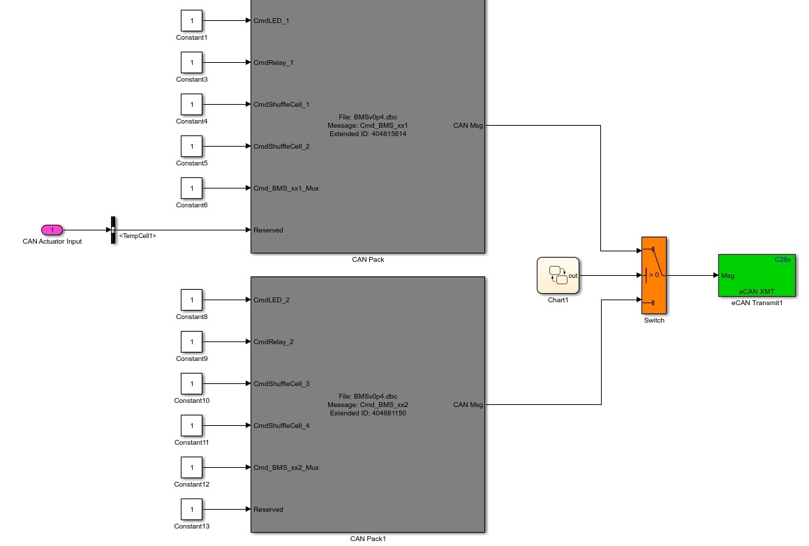
  • I am using MATLAB 2017a with the TI C2000 Embedded Coder Support Package. I use a dbc file to define the CAN Xmit & Rcv signals using the CAN Pack & Unpack blocks. According to the help:
    **Note CAN messages use the value of the Message identifier parameter in C28x CAN Transmit block for transmission even when you use the CAN Pack block to create the CAN message.**
    However the CAN frames transmitted are using the IDs from the CAN Pack Block, not the ID I have put in the CAN Xmit block. I am using a workspace variable to define the ID, (Message identifier field contains hex2dec(Status1_addr)) but it seems to be ignored by the CAN Xmit block in favor of the ID specified by the dbc file in the CAN Pack block.
    Am I missing something or is this a bug with these blocks?

    Thanks,
    Don
  • Hi,

    Please contact  MathWorks Technical Support with the necessary artifacts like model file, CAN dbc file.

    This will help us to better work on the problem.

    Regards,

    Venkatesh C

  • Don,
    I'm using 2016b and the Message ID is the value defined in C28X blocks according to the help. I wish I could use the Message ID defined in CAN Pack blocks, as you describe. I tried different ways but wasn't successful. That might be a new feature for 2017b, however you're saying it's not, according to the help. I would contact Mathwork technical team to see what the issue is.

    Regards,
  • Is there a sample model for PMSM encoder speed or positioning control

  • Hi Hayaoki,

    All of our examples are shown here (login required): https://www.mathworks.com/help/supportpkg/texasinstrumentsc2000/examples.html

    We have 2 examples specific to PMSM:

    HTH,

    -Brian

  • Thank you for your reference link.

    Is there a sample model of positioning control of PMSM using encoder using LAUNCHXL-F28379D

    For the model of sensorless control of MathWorks, is there any sample that can perform positioning control smoothly from the initial startup with an incremental encoder or the like?

    It is best to have a model that works with multiturn absolute encoder using CLB of peripheral of TMS320F28379.

  • Hi Hayaoki,

    We don't currently have a PMSM example for F28379D, but you should be able to use the one for F28377S. The library blocks we create are generic to F2837xS and F2837xD, so they apply for both F28377 and F28379. There are no unique blocks for F2837xD, but there is unique setup (such as a drop down where you can select CPU1 or CPU2)

    We also don't have an example like you describe, just the ones I linked before. I think this is something you would need to build.

    Cheers,

    -Brian

  • thank you for your answer.

    We will examine the positioning control by the incremental encoder by yourself.

    Functions unique to microcomputer in TMS320F28379S and TMS320F28379D CLI (Peripheral for absolute encoder) should be added in Simulink block.

    I want to know how to create blocks to add peripheral functions to TMS320F28379D.
    How to register TI's BiSS (encoder format) library with S-function?

    Or is there no plan to register multi-turn encoder functions in Simulink blocks? Per R2018A
  • Hi All,
    Does MATLAB/Simulink provide a Hex file (or something similar) after building the model? I would like to send it to the costumers so they can program the MCU directly.

    Thanks,

  • Hi Kash,

    I don't believe so. We generate C code (.c and related files) and use CCS to get it on the MCU. I'll double check with my development group.

    Could you provide a CCS project (including the C code from your MathWorks algorithm) to your customer?

    Cheers,

    -Brian

  • Brian,
    I'd like to give them a Hex file if it's possible.
    So the question is does CCS provide a hex file after building the software? if so, I can run the Simulink and it runs the CCS to flash the MCU then I can grab the Hex file generated by CCS from my Simulink model and give it to the costumer.

    What's your thought?
    --Kash