Other Parts Discussed in Thread: TMS320F28335, CONTROLSUITE, TMS320F28035, TMDSDOCK28379D, LAUNCHXL-F28379D, TMS320F28379D, TMS320F28379S
Save design time and get into production faster with C2000 MCU’s with MathWorks solutions.
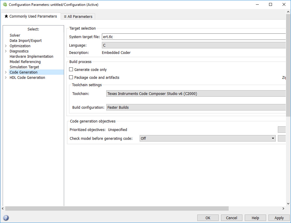
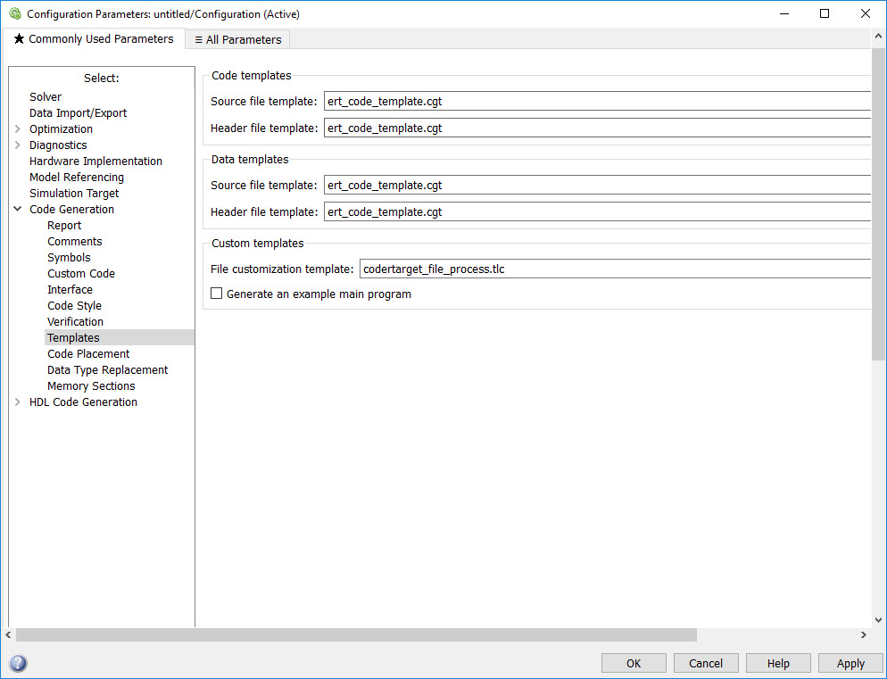
To begin you use MATLAB® and Simulink® to create and simulate your algorithms. Next you use Embedded Coder® to generate production code of your algorithms. Embedded Coder support for Texas Instruments C2000 includes:
- Automated build and execution
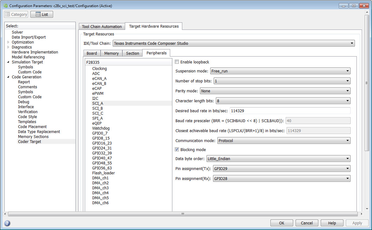
- Block libraries for on-chip and on-board peripherals such as ADC, digital I/O, ePWM, SPI, I2C, and more
- Real-time parameter tuning and logging using external mode
- Processor optimized code including DMC and IQMath libraries
- Ability to perform processor-in-the-loop (PIL) tests with execution profiling
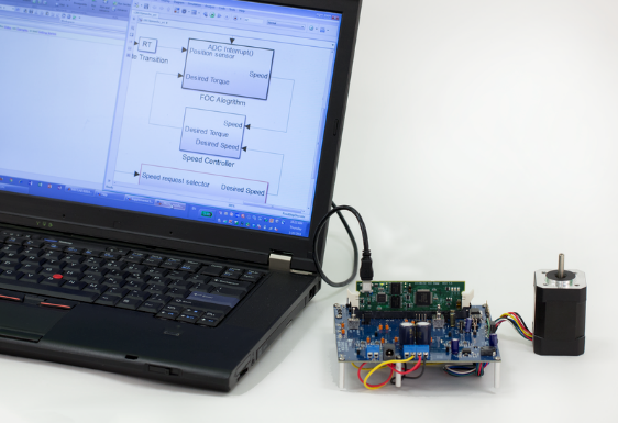
- Examples for motor control and power conversion that run on TI C2000 hardware
You can also generate code that runs on the Control Law Accelerator (CLA), a co-processor available on select TI Delfino and Piccolo processors.
For multicore systems, you can use SoC Blockset with C2000 Support for SoC Blockset to build your system architecture using processor, inter-processor communication, interrupt and I/O models, and simulate the architecture together with the algorithms. This allows you to partition algorithms between multiple cores to achieve design modularity and improve performance, and to account for issues like ADC-PWM synchronization and latency.
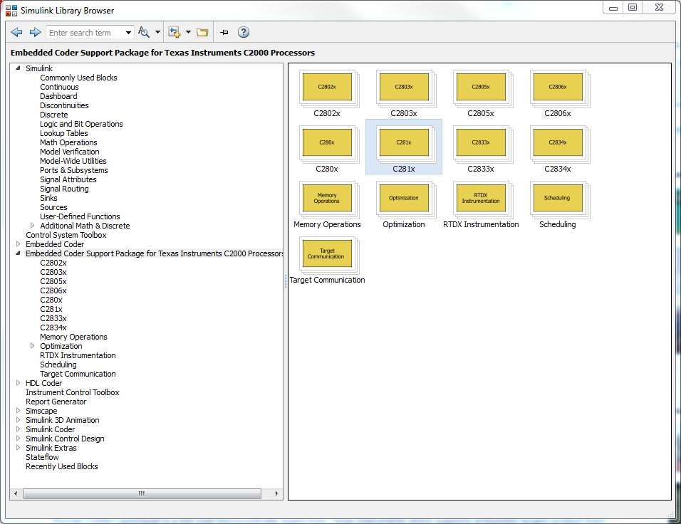
From within MATLAB you can access hardware support for Embedded Coder via the Add-On Explorer from the MATLAB toolstrip.
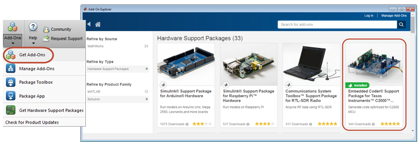
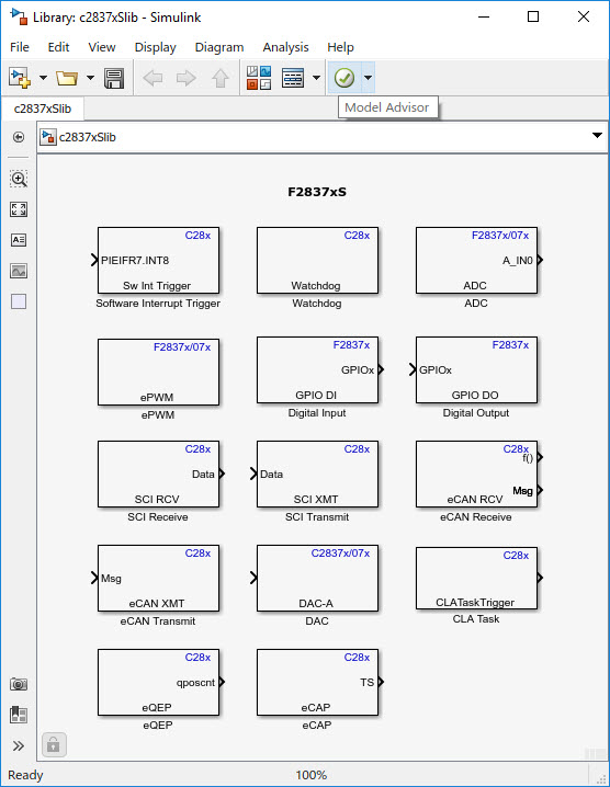
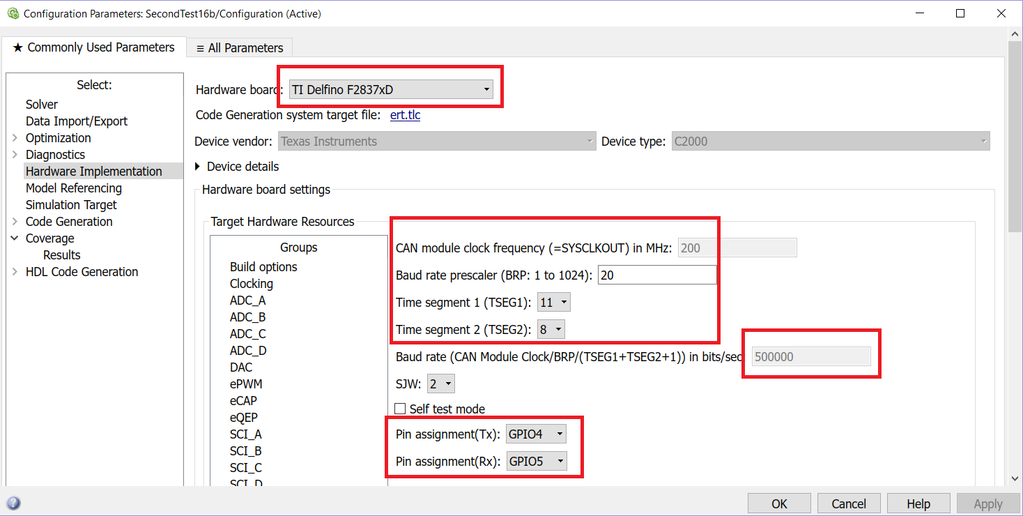
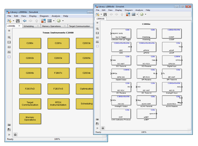
Search for C2000, and select to download and install free C2000 library blocks. You insert and configure the blocks, which include IO and various functions, in your Simulink model. Then you use Embedded Coder to generate production code of your algorithm and run it directly on your TI C2000 MCU. The library blocks include documentation, example models, and support C2000 Piccolo, Delfino, and Concerto families.
Note: Using Embedded Coder requires additional MathWorks software: MATLAB®, Simulink®, MATLAB Coder™, and Simulink Coder™.
You can also just generate production code of your algorithms which can be imported and integrated into an existing Code Composer Studio project.
--- ---
Here is more info including how-to videos and examples you can run with TI hardware kits:
-
How-to Videos and E2E posts:
-
YouTube: Programming TI C2000 Launchpad with Simulink (18:11)
-
YouTube: Using a TI F28069 LaunchPad with Simulink (16:32)
-
YouTube: Introduction to LAUNCHXL-F28069M Launchpad (Gautam Iyer, TI MVP)
-
YouTube: Introduction to LAUNCHXL-F28027 Launchpad (Gautam Iyer, TI MVP)
-
E2E: THE BEAST IS HERE: LAUNCHXL-F28379D (Gautam Iyer, TI MVP)
-
E2E: The Most Powerful C2000 Launchpad: LAUNCHXL-F28377S (Gautam Iyer, TI MVP)
-
-
-
Solution Overview:
-
Short videos (2-3 min): Embedded Coder Overview, Targeting TI Piccolo
-
Multicore simulation support using SoC Blockset with C2000 Support for SoC Blockset
-
Joint TI / MathWorks Sessions:
-
-
-
Details and Examples:
-
Content Updated 2020-11-02