This thread has been locked.

If you have a related question, please click the "Ask a related question" button in the top right corner. The newly created question will be automatically linked to this question.

Interrupt interfere maximum frequency


Hi all,

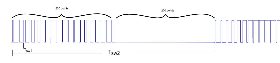
I am generating the Famous SPWM with the TMS320F2802x as shown by the picture.

My code is based on a simple way.....

I have a lookup table in the code that contain 200 values from 0 to 200 and my TBPRD value for frequency is 200 (that gives 300kHz)

I use the interrupt routine as seen by the code and I a

const int sineLookup[] = {
        0,
        0,
        0,
        0,
        0,
        1,
        1,
        2,
        2,
        3,
        4,
        5,
        6,
        7,
        8,
        10,
        11,
        12, blabla

      200,

        10,
        8,
        7,
        6,
        5,
        4,
        3,
        2,
        2,
        1,
        1,
        0,
        0,
};

frequency= 200; // define the TBPRD value for frequency 300kHz

interrupt void epwm1_isr(void)
{
    if(i==200)
    {
        i=0;
    }
    if(k==400)
    {
        k=0;
    }
    if(k<=199)
    {
          EPwm1Regs.CMPA.half.CMPA=sineLookup[i];
        EPwm1Regs.CMPB=frequency;
    }
    else
    {
        EPwm1Regs.CMPA.half.CMPA=0;
        EPwm1Regs.CMPB=0;
    }
    i++;
    k++;

    // Clear INT flag for this timer
    EPwm1Regs.ETCLR.bit.INT = 1;
    // Acknowledge this interrupt to receive more interrupts from group 3
    PieCtrlRegs.PIEACK.all = PIEACK_GROUP3;
}

void InitEPwm1Example()
{
    CLK_enablePwmClock(myClk, PWM_Number_1);
    EPwm1Regs.TBPRD=frequency;                        // Timer set for frequency (1/Tsw1....kHz)
    EPwm1Regs.TBPHS.half.TBPHS = 0;                    // Phase is 0
   // Setup TBCLK
   EPwm1Regs.TBCTL.bit.CTRMODE = TB_COUNT_UPDOWN; // Count up down
   EPwm1Regs.TBCTL.bit.PHSEN = TB_DISABLE;        // Master module
   EPwm1Regs.TBCTL.bit.PRDLD = TB_SHADOW;
   EPwm1Regs.TBCTL.bit.SYNCOSEL = TB_SYNC_IN;        // Sync flow through
   EPwm1Regs.CMPCTL.bit.SHDWAMODE = CC_SHADOW;
   EPwm1Regs.CMPCTL.bit.SHDWBMODE = CC_SHADOW;
   EPwm1Regs.CMPCTL.bit.LOADAMODE = CC_CTR_ZERO;    // Load on CTR=Zero
   EPwm1Regs.CMPCTL.bit.LOADBMODE = CC_CTR_ZERO;    // Load on CTR=Zero
   EPwm1Regs.TBCTL.bit.HSPCLKDIV=TB_DIV1;
   EPwm1Regs.TBCTL.bit.CLKDIV = TB_DIV1;          // Slow just to observe on the scope
   EPwm1Regs.AQCTLA.bit.CAU = AQ_CLEAR;             // Set PWM2A on Zero
   EPwm1Regs.AQCTLA.bit.CAD = AQ_SET;
   EPwm1Regs.AQCTLB.bit.CBU = AQ_CLEAR;           // Set PWM2B on Zero
   EPwm1Regs.AQCTLB.bit.CBD = AQ_SET;
   // Interrupt where the sine wave will be updated
   EPwm1Regs.ETSEL.bit.INTSEL = ET_CTR_PRD;      // Select INT on Zero event
   EPwm1Regs.ETSEL.bit.INTEN = 1;                 // Enable INT
   EPwm1Regs.ETPS.bit.INTPRD = ET_1ST;            // Generate INT on 1st event

}

Now the question....

For some reason the iteration number i and k (here 200 and 400) are directly related to the period Tsw2.

I try now to go from 1kHz to 10kHz and keeping the 200values per half period. But I can't. I HAVE TO use 20 and 40 iterations instead and

the TBPRD can go up to 6.

How can I keep the 400 values and go up to Tsw2=10kHz.

THere must be a way to make a better code to overcome that issue since the Microcontroller can do it.

  • Ioannis,

    You are operating outside the limits of the device.  Think about how many CPU clock cycles are available for each interrupt.  To keep all 400 points at 10kHz means your ISR must complete in 15 CPU cycles - that's barely enough for context save & restore.

    Regards,

    Richard 

  • Hi again,
    Thank you Richard for your reply!
    Well after spending some days on the Piccolo C2000 and with Delfino F28377S LaunchPad I still can not have the result I wan.
    Thus I tried to implement an other code idea using the ROM values (int16 *)0x3fe501 until (int16 *)0x3fe101 instead of the look up table above ( the idea is based on the direct digital synthesis). But in principal it is the same problem.
    Maybe someone out there knows whether it is a better idea to look for a different DPS or to do a better coding way approach.
    Kind regards,
    Ioannis
  • Hi Ioannis,

    If I understand correctly, you want to keep the number of samples per sine wave period fixed, while sweeping the frequency from low to high.  As you do that the time between adjacent samples will get smaller until eventually there is not enough time for the DSP to compute and output the next sample.  This puts an upper limit on achievable sine wave frequency whatever device you use, and whichever look-up table you use.

    Applications which do this usually reduce the number of samples per sine wave period as the frequency increases.  An example of an application which uses this method is a software frequency response analyzer

    You could, for example use every other sample in the look-up table once the frequency passes a certain threshold, then every third, fourth, ...and so on as the frequency increases.  Alternatively you might use more than one look-up table, of different sizes, switching from one to another depending on the frequency.  You'll need some sort of background routine to manage the frequency and pass something to the ISR to tell it which sample increment, or which look-up table, to use.  I think this is the only way.  

    I hope this helps.

    Regards,

    Richard