This thread has been locked.

If you have a related question, please click the "Ask a related question" button in the top right corner. The newly created question will be automatically linked to this question.

F28027 controller is locked (M5 LD2 is on not flashing)

Other Parts Discussed in Thread: CONTROLSUITE

Hello,

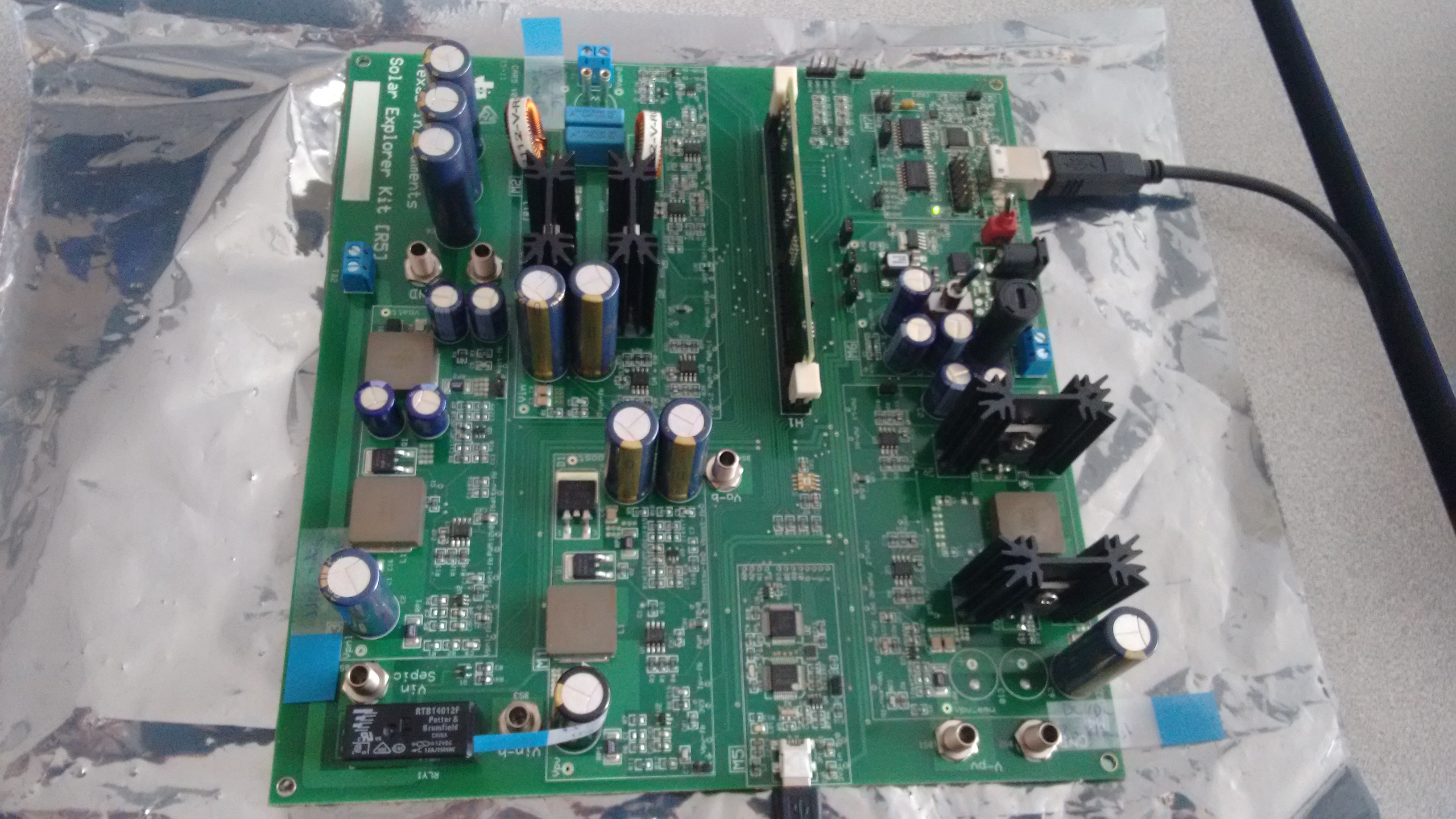
I have the C2000 Microcontrollers Solar Explorer Kit part #: TMDSSOLARPEXPKIT

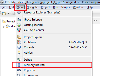
I am using Code Composer Studio Version: 6.1.1.00022

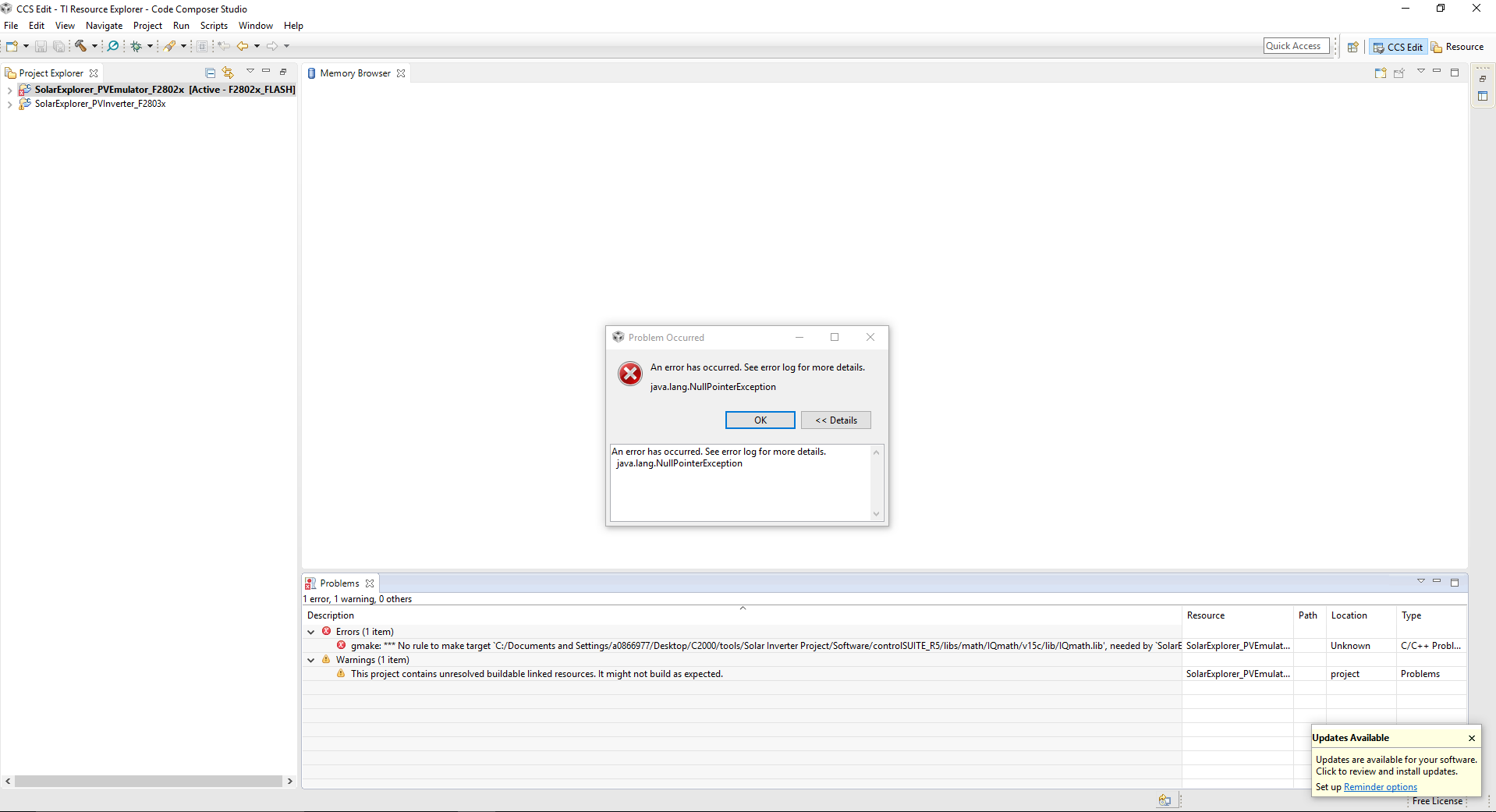
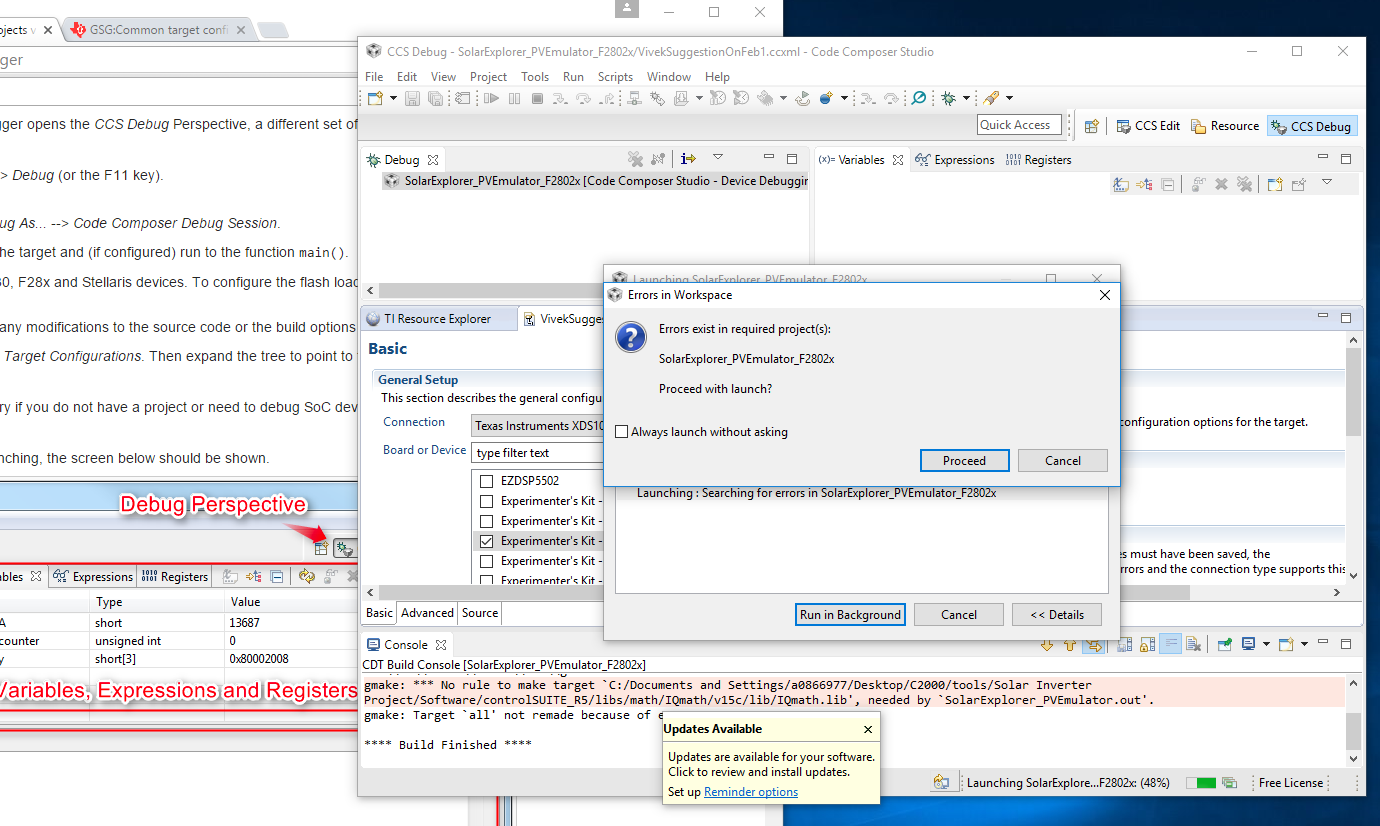
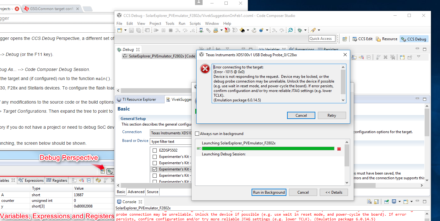
I have used the GUI example in ControlSuite before and it worked fine but for some reason I cannot operate it any longer. I noticed that the LED M5 LD2 is on but not flashing as it used to. I also get an error message when I try to upload code onto the board. This error message says that the controller is locked and needs to be unlocked either by resetting or by using a password.

Here's what I remember from the error: "Error connecting to the target: Device is not responding to the request. Device may be locked, or the emulator connection may be unreliable. Unlock the device if possible, and power-cycle the board. If error persists, confirm configuration and/or try more reliable JTAG settings."

I have checked the password and the Key7's password was FFFF based on an online forum I found. Right now, I suspect that the only way to unlock the board is to have a password from TI. 

Please, I am kindly asking for your reply at your earliest since I have deadlines soon which I need the board to get results.

Thank you for your time in advance.

Regards,

Ahmed

  • Hi Ahmed,

      I have checked the password and the Key7's password was FFFF based on an online forum I found. Right now, I suspect that the only way to unlock the board is to have a password from TI. 

    Did you check the value at password locations in Flash to confirm these are indeed  0xFFFFFFFF ? You should check that. Providing value 0xFFFF as KEY will not unlock the device.

    Please note that TI does not program any password in device. All the devices shipped from TI have default password value as 0xFFFFFFFF which means device is not LOCK.  If due to some reason these password values get changed during flash operation and the value programmed is not known then device can not be UNLOCK and it need to be replaced.

    Regards,

    Vivek Singh

  • Hi Vivek,

    Thank you for you prompt reply.

    Please see attached photo for the code security password list on chip.

    Please note that I am a beginner in CCS and with TI in general so if I am looking in the wrong place please tell me the exact steps on how to navigate to the appropriate place.

    Also, could you please tell me what causes the controller to be locked? This is important as I might end up replacing the part, if there is no other way to unlock, and I have to avoid locking it again.

    By the way, here's the exact error message that I am getting when I try to upload code onto the chip:

    C28xx: Error connecting to the target: (Error -1015 @ 0x0) Device is not responding to the request.  Device may be locked, or the debug probe connection may be unreliable. Unlock the device if possible (e.g. use wait in reset mode, and power-cycle the board). If error persists, confirm configuration and/or try more reliable JTAG settings (e.g. lower TCLK). (Emulation package 6.0.14.5)

    Thanks,
    Ahmed

  • Hi Ahmed,

    These are values for KEYx register which user provides via CCS Flash-plugin GUI. What I was referring was to see the content of CSM password locations in Flash via CCS memory browser window.  To open memory browser in CCS, click on "View -> Memory Browser" in CCS GUI and this will open the memory browser window where you can enter any address to check the content.

    Address for CSM password location in Flash are (0x3F 7FF8 - 0x3F 7FFF). Please check the value at these address and these are not 0xFFFF_FFFF then device is LOCK. It could have happened by some wrong flash programming operation or power loss during flash operation.

    Regards,

    Vivek Singh

  • Hi Vivek,

    Thank you for your continued assistance.

    I was trying to do what you said but when I click on 'Memory Browser' I get the error message in the attached pic.

    I searched the error message online and I got an answer in the following link but I am not sure how it is relevant to our problem.

    Link: stackoverflow.com/.../what-is-a-null-pointer-exception-and-how-do-i-fix-it

    Please Advise,

    Ahmed

  • Ahmed,

    That is strange. It should not give any error. Did you try restarting CCS to see if that helps.

    You may also want to go through following link to get some help on CCS debug -

    http://processors.wiki.ti.com/index.php/GSG:Debugging_projects_v5#Launching_the_debugger

    Regards,

    Vivek Singh

  • Hi Vivek,

    Thank you for your last reply.

    Unfortunately I was unable to look into the password values in CCS memory watch window.

    I tried to go through the debug process shown in the link you provided, but I was unable to complete the it as whenever I try to run the debug I get the errors shown in the attached images. When the error in the first image appeared I clicked "Proceed", then the error in the second image appears. I also ran the Connection Test and the results of the test are pasted after the images. 

    You mentioned that you will be asking someone from marketing regarding the replacement. Were you able to ask them? Please let me know.

    P.S: In the target configuration, I set up the target as the "Experimenter's Kit - Piccolo F28027" and the connection I chose was "Texas Instruments XDS100v1 USB Debug Probe".

    Thank you,

    Ahmed

    Connection Test Results:

    [Start: Texas Instruments XDS100v1 USB Debug Probe_0]

    Execute the command:

    %ccs_base%/common/uscif/dbgjtag -f %boarddatafile% -rv -o -F inform,logfile=yes -S pathlength -S integrity

    [Result]


    -----[Print the board config pathname(s)]------------------------------------

    C:\Users\AMEDDA~1\AppData\Local\TEXASI~1\
    CCS\ti\0\0\BrdDat\testBoard.dat

    -----[Print the reset-command software log-file]-----------------------------

    This utility has selected a 100- or 510-class product.
    This utility will load the adapter 'jioserdesusb.dll'.
    The library build date was 'Sep 4 2015'.
    The library build time was '21:59:23'.
    The library package version is '6.0.14.5'.
    The library component version is '35.35.0.0'.
    The controller does not use a programmable FPGA.
    The controller has a version number of '4' (0x00000004).
    The controller has an insertion length of '0' (0x00000000).
    This utility will attempt to reset the controller.
    This utility has successfully reset the controller.

    -----[Print the reset-command hardware log-file]-----------------------------

    The scan-path will be reset by toggling the JTAG TRST signal.
    The controller is the FTDI FT2232 with USB interface.
    The link from controller to target is direct (without cable).
    The software is configured for FTDI FT2232 features.
    The controller cannot monitor the value on the EMU[0] pin.
    The controller cannot monitor the value on the EMU[1] pin.
    The controller cannot control the timing on output pins.
    The controller cannot control the timing on input pins.
    The scan-path link-delay has been set to exactly '0' (0x0000).

    An error occurred while hard opening the controller.

    -----[An error has occurred and this utility has aborted]--------------------

    This error is generated by TI's USCIF driver or utilities.

    The value is '-150' (0xffffff6a).
    The title is 'SC_ERR_FTDI_FAIL'.

    The explanation is:
    One of the FTDI driver functions used during
    configuration returned a invalid status or an error.

    [End: Texas Instruments XDS100v1 USB Debug Probe_0]

  • Ahmed,

    Vivek brought this to my attention.  I'll get into contact with you offline to work on a replacement soln.

    Best,

    Matthew

  • Closing the thread !!