This thread has been locked.

If you have a related question, please click the "Ask a related question" button in the top right corner. The newly created question will be automatically linked to this question.

Software Watchdog configuration


Good morning,

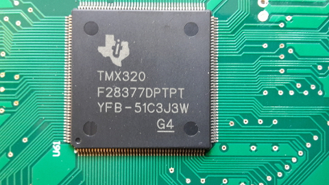
I'm trying to configure a software Watchdog in my tms320f28337D.

I've read the manual seen the Control Suite example but I'm having problems to understand if my configuration is correct.

I'm using the register:

WdRegs.WDCR.all = 0x0028;

and, acording with the manual:

WdRegs.WDCR.bit.WDPS = (.....)

These bits configure the watchdog counter clock (WDCLK) rate relative to INTOSC1/512:


000 WDCLK = INTOSC1/512/1
001 WDCLK = INTOSC1/512/1
010 WDCLK = INTOSC1/512/2
011 WDCLK = INTOSC1/512/4
100 WDCLK = INTOSC1/512/8
101 WDCLK = INTOSC1/512/16
110 WDCLK = INTOSC1/512/32
111 WDCLK = INTOSC1/512/64

So, being the INTOSC1 the internal oscilator with 10 Mhz, I should have around 10MHz / 512 / 1 = 19,53 KHz  ~= 51,2 useconds as the minimum time and 

10MHz / 512 / 64 = 305,17 Hz  ~= 3,3 mseconds as te maxium time available for the watchdog reset interruption.

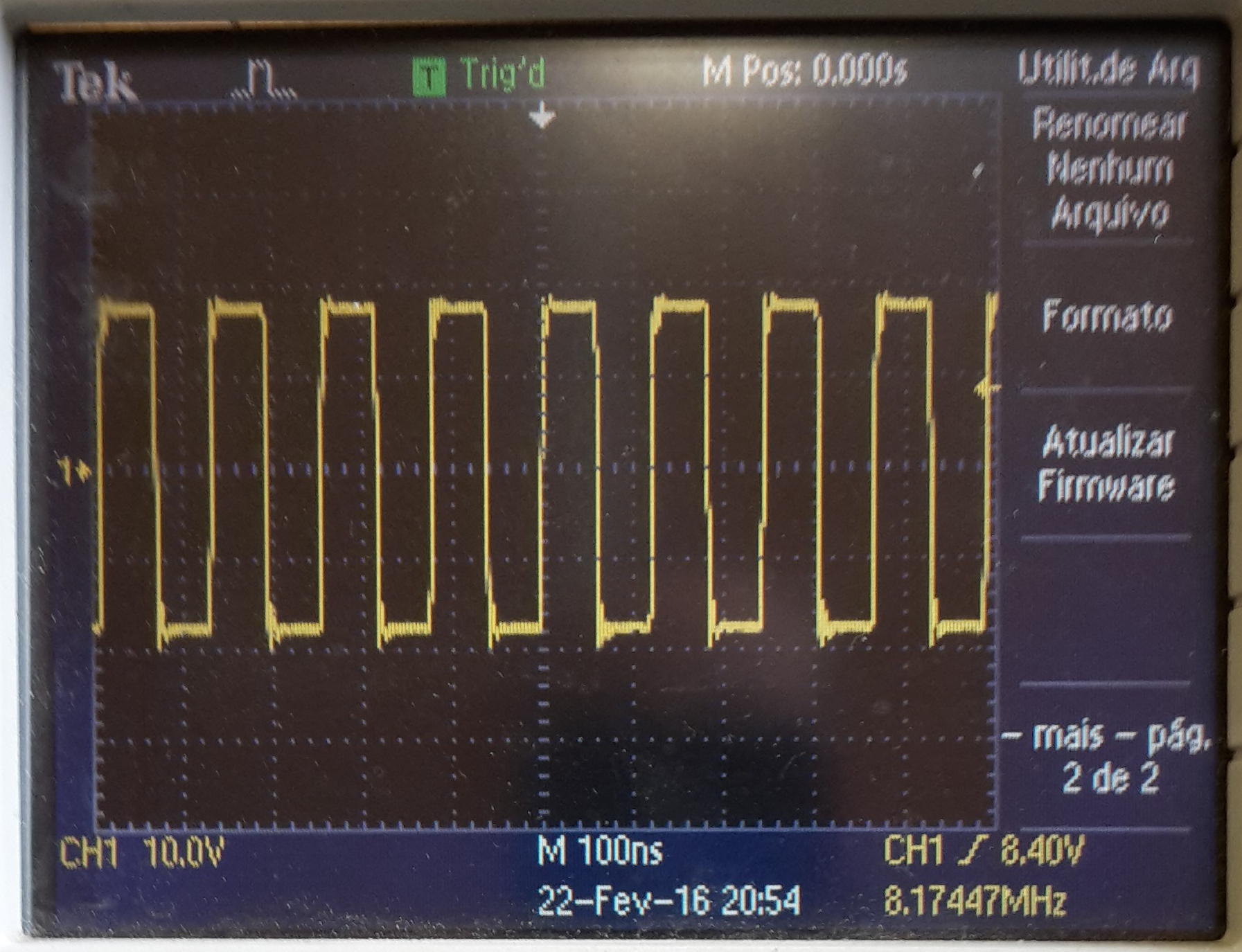
But in my code (and in the Control Suite example), I'm getting 15 mseconds as the minimum time and 1 second as the maximum time for the watchdog interruption.

Am I missing something? Some configuration? 

My best regards, Jorge 

  • Hi,

    Good morning !!

    Please refer following E2E forum post which has discussion on same topic.

    Hope this helps. If not, let us know.

    Regards,

    Vivek Singh

  • Hello Vivek,

    I've read the post made about this subject but still the times that I'm getting don't match up.

    In the post:

    "The Technical Reference Manual says on page 111 that the clock source is INTOSC1. This is a 10MHz oscillator and passes through a 512 prescaler. Then, the watchdog input frequency is 10 MHz / 512 = 19531,25 Hz. Am I right?

    Besides the 512 fixed prescaler, there's another one controlled by the WDCR(WDPS(2:0)) bit, which can be 1, 2, 4, 8, 16, 32 or 64.

    So, assuming that the WDPS bit is set to 64, the 8-bit Watchdog Counter input will be: (10 MHz / 512)/64 = ~305 Hz and the time period is ~3,2 ms. To overflow the counter, it takes 3,2 ms * 256 = ~835 ms."

    So I should be getting a watchdog reset time from 13,10 ms(minimum) to 814,1 ms.(maximum)

    But I'm actually getting 16,2 mseconds (minimum) and 1,032 seconds(maximum)


    My source code based on the control suite as a flag that I use to disable the ServiceDog() function and to start the time count.

    I'm using an Oscilloscope to measure the time bettween the last Watchdog Counter reset and the actual Watchdog interruption.

    void main(void)
    {

    // unsigned long delay;
    // Step 1. Initialize System Control:
    // PLL, WatchDog, enable Peripheral Clocks
    // This example function is found in the F2837xD_SysCtrl.c file.
    InitSysCtrl();

    // Step 2. Initialize GPIO:
    // This example function is found in the F2837xD_Gpio.c file and
    // illustrates how to set the GPIO to it's default state.
    InitGpio();
    GPIO_SetupPinMux(86, GPIO_MUX_CPU1, 0);
    GPIO_SetupPinOptions(86, GPIO_OUTPUT, GPIO_PUSHPULL);

    // Step 3. Clear all interrupts and initialize PIE vector table:
    // Disable CPU interrupts
    DINT;

    // Initialize the PIE control registers to their default state.
    // The default state is all PIE interrupts disabled and flags
    // are cleared.
    // This function is found in the F2837xD_PieCtrl.c file.
    InitPieCtrl();

    // Disable CPU interrupts and clear all CPU interrupt flags:
    IER = 0x0000;
    IFR = 0x0000;

    // Initialize the PIE vector table with pointers to the shell Interrupt
    // Service Routines (ISR).
    // This will populate the entire table, even if the interrupt
    // is not used in this example. This is useful for debug purposes.
    // The shell ISR routines are found in F2837xD_DefaultIsr.c.
    // This function is found in F2837xD_PieVect.c.
    InitPieVectTable();

    // Interrupts that are used in this example are re-mapped to
    // ISR functions found within this file.
    EALLOW; // This is needed to write to EALLOW protected registers
    PieVectTable.WAKE_INT = &wakeint_isr;
    EDIS; // This is needed to disable write to EALLOW protected registers

    // Step 4. User specific code, enable interrupts:
    // Clear the counters
    WakeCount = 0; // Count interrupts
    LoopCount = 0; // Count times through idle loop
    // Connect the watchdog to the WAKEINT interrupt of the PIE
    // Write to the whole SCSR register to avoid clearing WDOVERRIDE bit
    EALLOW;
    WdRegs.SCSR.all = BIT1;
    EDIS;

    // Enable WAKEINT in the PIE: Group 1 interrupt 8
    // Enable INT1 which is connected to WAKEINT:
    PieCtrlRegs.PIECTRL.bit.ENPIE = 1; // Enable the PIE block
    PieCtrlRegs.PIEIER1.bit.INTx8 = 1; // Enable PIE Group 1 INT8
    IER |= M_INT1; // Enable CPU INT1
    EINT; // Enable Global Interrupts

    // Reset the watchdog counter
    ServiceDog();

    // Enable the watchdog
    EALLOW;
    WdRegs.WDCR.all = 0x0028;
    EDIS;

    GPIO_WritePin(86, 0);
    // Step 6. IDLE loop. Just sit and loop forever (optional):
    for(;;)
    {
    LoopCount++;

    // Uncomment ServiceDog to just loop here
    // Comment ServiceDog to take the WAKEINT instead
    if(TurnOffFlag == 0)
    {
    ServiceDog();
    }
    else
    {
    GPIO_WritePin(86, 1);
    for(;;);
    }

    }
    }

    // Step 7. Insert all local Interrupt Service Routines (ISRs) and functions here:
    // If local ISRs are used, reassign vector addresses in vector table as
    // shown in Step 5

    __interrupt void wakeint_isr(void)

    {
    WakeCount++;

    GPIO_WritePin(86, 0);
    TurnOffFlag=0;

    // Acknowledge this interrupt to get more from group 1
    PieCtrlRegs.PIEACK.all = PIEACK_GROUP1;
    }


  • Hi,

    Thanks for providing further detail and the code. Time difference you are seeing is a lot and should not happen.

    I'm using an Oscilloscope to measure the time between the last Watchdog Counter reset and the actual Watchdog interruption.

    I assume you are checking the time between GPIO86 going HIGH to LOW. Correct? Can you attached the scope screen shot for this measurement.

    Regards,

    Vivek Singh

  • Hello Vivek,

    Regarding your question:

    "I assume you are checking the time between GPIO86 going HIGH to LOW. Correct? Can you attached the scope screen shot for this measurement."

    Yes, you are correct.

    To understand what is going on, I've used the XCLKOUT feature of the DSP and tested de systems frequency using the XCLKOUTSEL bit.

    For my DSP PLLSYSCLK I've got 25 MHz, witch is expected. I'm running at 200 MHz (with a external ocilator of 20 MHz) and the XCLKOUTDIVSEL was set for 1/8.

    This means that 25 MHz = 200 MHz / 8

    So far so good.

    But when I tested the INTOSC1 (reference for the watchdog timer), I got 8.17 MHz instead of 10 MHz.

    For this test I set the XCLKOUTDIVSEL for 1/1.

    I'm sending a screenshot for you to see.

    You can see the INTOSC1 frequency in the bottom right corner of the picture.

    This frequency explains my time drift for the watchdog timer.

    Is there a way to adjust the internal Oscilator to get the correct 10 Mhz frequency?

    My best regards, Jorge

  • Hi Jorge,

    Can you provide the information mention on the top of the device (you could take a pic and attach) to know which version of device you are using.

    Also the above experiments you are trying only when JTAG (CCS) is connected or also in stand-alone mode. If you have only tried with JTAG (CCS) connected then please try stand-alone mode as well and see if that shows different result.

    Regards,

    Vivek Singh

  • Hello Vivek,

    I've tested the configuration with and without JTAG connected (booting from FLASH/ stand alone)

    The times I've got were the same.

    I've made the same test to another 2 dsp that I have and got different values: 9,46 MHz for both, instead of 10 MHz.

    The picture of the top of my dsp is this:

  • Hello again Vivek,

    Do you have any information about this issue?

    I'm getting internal oscillator frequencies bellow the 5% average admited (from 9.7 Mhz to 10.3 Mhz).

    Is possible that the adjust values from the internal oscillator were change (by memory corruption, for example)?

    My best regards, Jorge

  • Hi Jorge,

    We'll have our OSC expert to look into this.

    Regards,

    Vivek Singh

  • Hello Jorge,

    For TMX devices the internal oscillator may not be trimmed. Please see p. 9 of the silicon errata document re: internal oscillator. www.ti.com/.../sprz412f.pdf

    Please let me know if you further clarification re: the oscillator.

    Best Regards,
    Adam Dunhoft
  • Hello Adam,

    That seems to be correct.

    Thank you for your support.

    My best regards, Jorge