Dear Supplier,
My application is a switching power converter and i'm using TMS320F28035PAGT to control a half-bridge LLC converter and a synchronous rectifier.
EPWM3A and EPWM3B drive the half-bridge power MOSFETs.
EPWM4A and EPWM4B drive the synchronous rectifier MOSFETs.
When using imemediate load for the PRDLD register it works fine:
(*ePWM[4]).TBCTL.bit.PRDLD = TB_IMMEDIATE;
When using shadow register load for the PRDLD register it shows the problem described below:
(*ePWM[4]).TBCTL.bit.PRDLD = TB_SHADOW
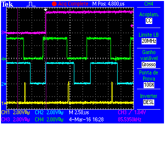
A) EPWM4 TRIPZONE OST CAN BE ACTIVATED AND CLEARED SUCESSIVELY WITHOUT ANY PROBLEM
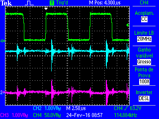
GREEN - EPWM3A / CYAN - EPWM4B / MAGENTA - EPWM4A

GREEN - EPWM3A / CYAN - EPWM4B / MAGENTA - EPWM4A
GREEN - EPWM3A / CYAN - EPWM4B / MAGENTA - EPWM4A
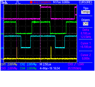
B) WHEN EPWM3 AND EPWM4 TRIPZONE OST ARE ACTIVATED BOTH OPERATES CORRECTLY
GREEN - EPWM3A / CYAN - EPWM4B / MAGENTA - EPWM4A
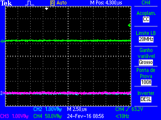
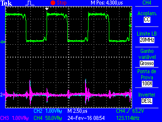
C) WHEN EPWM3 AND EPWM4 TRIPZONE OST ARE CLEARED EPWM3 RETURNS OPERATING CORRECTLY BUT EPWM4A AND EPWM4B DO NOT RETURN TO PWM OPERATION.
EPWM4A STAYS AT LOW LEVEL AND EPWM4B STAYS HIGH LEVEL
GREEN - EPWM3A / CYAN - EPWM4B / MAGENTA - EPWM4A
What can be the cause of this wrong behavior?
How to avoid such behavior using shadow mode for EPWM4 PRDLD
(*ePWM[4]).TBCTL.bit.PRDLD = TB_SHADOW
******** PWM 4 CONFIGURATION *********************
(*ePWM[4]).TBPRD = period;
(*ePWM[4]).CMPA.half.CMPA = period >> 1;
(*ePWM[4]).CMPB = period >> 2;
(*ePWM[4]).TBPHS.half.TBPHS = 60;
(*ePWM[4]).TBCTR = 0;
(*ePWM[4]).TBCTL.bit.CTRMODE = TB_COUNT_UP;
(*ePWM[4]).TBCTL.bit.PHSEN = TB_ENABLE; //TB_DISABLE;
(*ePWM[4]).TBCTL.bit.SYNCOSEL = TB_SYNC_IN;
(*ePWM[4]).TBCTL.bit.HSPCLKDIV = TB_DIV1;
(*ePWM[4]).TBCTL.bit.CLKDIV = TB_DIV1;
(*ePWM[4]).CMPCTL.bit.LOADAMODE = CC_CTR_ZERO;
(*ePWM[4]).CMPCTL.bit.LOADBMODE = CC_CTR_ZERO;
(*ePWM[4]).CMPCTL.bit.SHDWAMODE = CC_SHADOW;
(*ePWM[4]).CMPCTL.bit.SHDWBMODE = CC_SHADOW;
(*ePWM[4]).AQCTLA.bit.ZRO = AQ_SET;
(*ePWM[4]).AQCTLA.bit.CAU = AQ_CLEAR;
(*ePWM[4]).AQCTLB.bit.CAU = AQ_SET;
(*ePWM[4]).AQCTLB.bit.PRD = AQ_CLEAR;
(*ePWM[4]).DBCTL.bit.IN_MODE = DBA_ALL;
(*ePWM[4]).DBCTL.bit.OUT_MODE = DB_FULL_ENABLE;
(*ePWM[4]).DBCTL.bit.POLSEL = DB_ACTV_HIC;
(*ePWM[4]).DBRED = 46;
(*ePWM[4]).DBFED = 46;
EALLOW;
(*ePWM[4]).TBCTL.bit.SWFSYNC = 1;
EDIS;