This thread has been locked.

If you have a related question, please click the "Ask a related question" button in the top right corner. The newly created question will be automatically linked to this question.

SPI proplem f2812

Other Parts Discussed in Thread: TPIC8101

hi all,

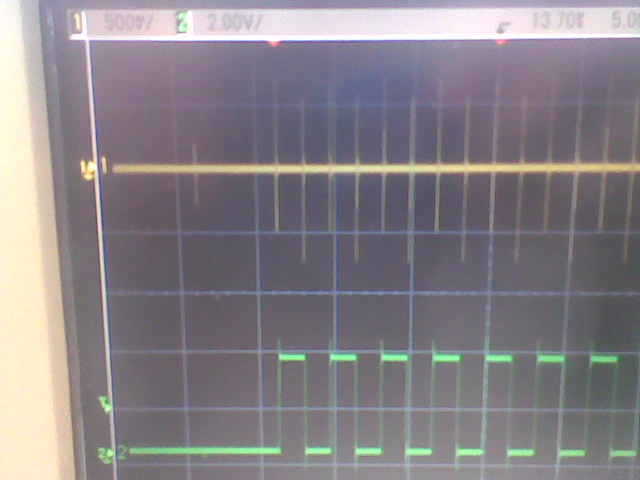
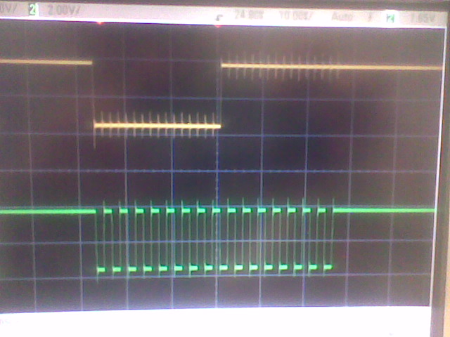
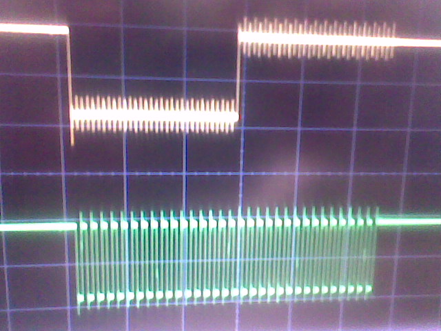
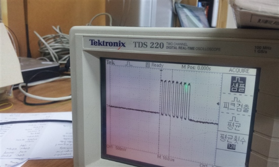
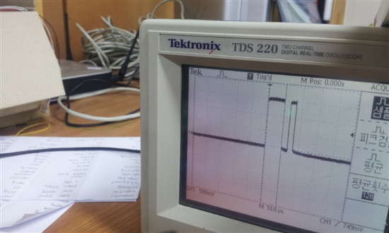
im using the SPI of f2812, the problem is, i can see the Clock, but the data output, no,,,here in the picture you can the clock, but the data no,,,,

just peak at the start of the clock and ofcourse , and the ened of the clock, but nothing else,


  • Hi Hasan,

    really hard to say where your problem is..

    how is your hardware connected to spi pins?
    have you set proper settings for the pins?

    Here is my send function to send something over spi

    Uint16 spi_xmit(Uint16 a)
    {
        SpiaRegs.SPITXBUF=a<<8;
        while(SpiaRegs.SPISTS.bit.INT_FLAG != 1);     //Wait until the RXBUF has received last bit
        return (SpiaRegs.SPIRXBUF<<8);
    }

    because spitxbuf is 8 bit wide there is a bitshift operation at the beginning.

    and here the spi init function

    void InitSPI(void)
    {   
        SpiaRegs.SPICCR.all =0x0007;                 // Reset on, rising edge, 8-bit char bits 
        SpiaRegs.SPICTL.all =0x000E;                 // Enable master mode, shift phase,
                                                     // enable talk, and SPI int disabled.
        SpiaRegs.SPIBRR =0x000C;                     // 3.125 MBit/s   (37.5 MHz / 0x0C)                                
        SpiaRegs.SPICCR.all =0x0087;                 // Relinquish SPI from Reset  
        SpiaRegs.SPIPRI.bit.FREE = 1;                // Set so breakpoints don't disturb xmission 

    }

    and at the end the settings for the gpios

    // SPI Interface --------------------------------------------
       GpioMuxRegs.GPFMUX.bit.SPISIMOA_GPIOF0 = 1;    // SPISIMOA
       GpioMuxRegs.GPFMUX.bit.SPISOMIA_GPIOF1 = 1;    // SPISOMIA
       GpioMuxRegs.GPFMUX.bit.SPICLKA_GPIOF2  = 1;  // SPICLKA
       GpioMuxRegs.GPFMUX.bit.SPISTEA_GPIOF3  = 0;  // IO
       GpioMuxRegs.GPFDIR.bit.GPIOF3 = 1;            // Set as Output        
       GpioDataRegs.GPFSET.bit.GPIOF3 = 1;            // Init as '1'
       GpioMuxRegs.GPFMUX.bit.SCIRXDA_GPIOF5  = 0;  // IO
       GpioMuxRegs.GPFDIR.bit.GPIOF5 = 1;            // Set as Output        
       GpioDataRegs.GPFSET.bit.GPIOF5 = 1;            // Init as '1'  
    /* Comment:
       Normaly the SPISTEA pin (GPIOF3) is not set as an output.
       But the desired hardware configuration needs a second chipselect
       pin. If we set the SPISTEA pin to normal operation it will be
       driven to low if there is transmission on SPI in master mode.
       To avoid bus conflict if we want to read or write to the
       second serial eeprom, we have to generate the chipselect manually
       for each device
    */
    //-----------------------------------------------------------


    Regards

    Eggi

  • Hi Eggi;

    actually i discovered where is the problem, but i dont know how to solve it,

    the initialization of the SPI,

        SpiaRegs.SPICCR.bit.SPICHAR = 0x7 ;   8-bit characters,,,,,, NOT WORKING

        SpiaRegs.SPICCR.bit.SPICHAR = 0xF ;   16-bit characters,,,,,, WORKING


    its like that    A= 0x1000;   //it sends 1 first
    its like that    A= 0x0001    // it sends 1 in the end,

    the problem, is in the second case, which is considered 8-bit, the output of SPI, is around 100mv, as the image i sent earlier,

    THE MAIN PROBLEM, the Slave part, is only 8-bit,,,,,,,so it always receive zeroes,,,,, :(


    i dont know what is the problem, soooo strange,

  • For SPI, you must write your data in the most significant bits of the TXBUF.  Then, you read from the least significant bits of the RXBUF.  Could that be the issue?

  • thanks for your reply,

    but this is not the issue,

    the issue is, when i make the transmitted data 8-bit,,,,,, the output pin,,,, give me peaks like the first image,,,,,,,, so, no output at all

    and when i make the setting to 16-bit, the output is working fine,,,,,

        SpiaRegs.SPICCR.bit.SPICHAR = 0xF


    why i dont make it 16-bit,,,because the SPI-slave, is only 8-bit,


    Regards

    Hasan

  • this is my new init


        EALLOW;
        GpioMuxRegs.GPFMUX.all |= 0x000F;  
          EDIS;
        SpiaRegs.SPIFFTX.all=0xE040;
        SpiaRegs.SPIFFRX.all=0x204f;
        SpiaRegs.SPIFFCT.all=0x0;
          SpiaRegs.SPICCR.all =0x0008;                
        SpiaRegs.SPICCR.bit.SPICHAR = 0x7;
          SpiaRegs.SPICTL.all =0x0006;
          SpiaRegs.SPIBRR =0x007F;                        
        SpiaRegs.SPICCR.all =0x009F;               
        SpiaRegs.SPICCR.bit.SPICHAR = 0x7;     // here is the PROBLEM      ,,, when its 0F, its working, fine, when its 07 Not WORKING
        SpiaRegs.SPIPRI.bit.FREE = 1;              
        SpiaRegs.SPICCR.bit.CLKPOLARITY = 1;
        SpiaRegs.SPICTL.bit.CLK_PHASE = 0;

  • Try this:

    SpiaRegs.SPITXBUF = 0xFFFF;


  • for confirmation, you want me to send th 0xFFFF, write,


  • last image, after i sent 0xFFFF ,

    while its connect to the slave

  • In this case, is SPICHAR set to 0x7 (8-bits) or 0xF (16-bits)?  I see 16 clock cycles, but it looks like the data is 0x00FF.

  •     EALLOW;
        GpioMuxRegs.GPFMUX.all |= 0x000F;    // Select GPIOs to be SPI pins     nsdqumdsrj
                                         // Port F MUX - x000 0000 0000 1111nsdqumdsrj
          EDIS;
    // Initialize SPI FIFO registersnsdqumdsrj
        SpiaRegs.SPIFFTX.all=0xE040;
        SpiaRegs.SPIFFRX.all=0x204f;
        SpiaRegs.SPIFFCT.all=0x0;
          SpiaRegs.SPICCR.all =0x0008;                 // Reset on, rising edge, 8-bit char bits  nsdqumdsrj
        SpiaRegs.SPICCR.bit.SPICHAR = 0x7;
          SpiaRegs.SPICTL.all =0x0006;                 // Enable master mode, normal phase,nsdqumdsrj
                                                     // enable talk, and SPI int disabled.nsdqumdsrj
          SpiaRegs.SPIBRR =0x007F;                        
        SpiaRegs.SPICCR.all =0x009F;                 // Relinquish SPI from Reset   nsdqumdsrj
        SpiaRegs.SPICCR.bit.SPICHAR = 0x7;
        SpiaRegs.SPIPRI.bit.FREE = 1;                // Set so breakpoints don't disturb xmissionnsdqumdsrj
    //(CLKPOLARITY,CLK_PHASE )01 10??74HC595,00?11???  ???? nsdqumdsrj
        SpiaRegs.SPICCR.bit.CLKPOLARITY = 1;
        SpiaRegs.SPICTL.bit.CLK_PHASE = 0;


    strange, i did make it 07,,,,,,but i write directly the 0xFFFF to the SPIBUF,

    i dont know,,,,, its really driving me crazy

  • last one was when im putting the setting, at   0F  16-bit ,,,,,,,,it transmitt write, the 0xFFFF, but in the Lowest bits


    iwhy is that,,,,,, when it was 07, it transmit only the 0xFF, and when its 0F, it transmit 0xFFFF but in the lowest,,,,,

    Always transmit the Full as the half, and the Clock is double than the setting, and when its normal i mean when the clock is right, the no output data come out


    no idea,   does anyone faced that before :(


    regards

    Hasan

  • cio Tutti

    i think, the problem as follow,,,

    the when i have 8-bit clock, i got 16-bit output,,,,, i mean, the output when its rising edge and falling edge,,,,,,,NOT only with rising edge,,,,


  • hello. because i`m korean, i don`t write english well.

    please, understanding. ^^

    Maybe. I thinking...

    if you send a data(1byte)....

    can you use "SpiaRegs.SPITXBUF = c<<8;" ?

    c is 8bit data. example c= 0x01;

    it`s 8 clock. and sending data

  • Hi

    I am facing the same issue,please share with me if you got solution for the above issue

  • See the code below, it is working fine

    void spi_init()
    {
    // Initialize SPI FIFO registers
    SpiaRegs.SPIFFTX.all=0xE040;
    SpiaRegs.SPIFFRX.all=0x204f;
    SpiaRegs.SPIFFCT.all=0x0;

    SpiaRegs.SPICCR.all =0x47; // Reset on, rising edge, 8-bit char bits
    SpiaRegs.SPICTL.all =0x06; // Enable master mode, normal phase,
    SpiaRegs.SPIBRR = 0x20;//0x7f; //baud rate
    SpiaRegs.SPICCR.all =0x0C7; // Relinquish SPI from Reset // Bit 4 loop back mode disabled
    }


    Uint16 rtc_read(Uint16 mem) //read from DS1306 RTC
    {
    N8 rd_rtc;
    ENABLE_RTC; //chip select

    mem <<= 8; //shift left 8 times
    SpiaRegs.SPITXBUF = mem; //writing
    spi_timeout = 0;
    while((SpiaRegs.SPIFFRX.bit.RXFFST == 0x0)/* && (spi_timeout < SPI_TIME)*/);
    rd_rtc = SpiaRegs.SPIRXBUF ; //& 0xff; //dummy read

    SpiaRegs.SPITXBUF = 0; //dummy write
    spi_timeout = 0;
    while((SpiaRegs.SPIFFRX.bit.RXFFST == 0x0) /*&& (spi_timeout < SPI_TIME)*/);
    rd_rtc = SpiaRegs.SPIRXBUF & 0xff;
    DISABLE_RTC;
    /*if(spi_timeout >= SPI_TIME) { spi_error = 1; } */
    return(rd_rtc);
    }

    The bits goes out (write) on MSB side and comes in (read) at LSB.

  • Hi

    Thanks for your sugession.

    Actually  i need to send 5 8bit messages  to a slave from f2812 .Each message is having command and data.The command is 2 or 3 bits and remaining are data bits.in your code after sending 8 bit data

    mem <<= 8; //shift left 8 times
    SpiaRegs.SPITXBUF = mem; //writing
    spi_timeout = 0;
    while((SpiaRegs.SPIFFRX.bit.RXFFST == 0x0)/* && (spi_timeout < SPI_TIME)*/);
    rd_rtc = SpiaRegs.SPIRXBUF ; //& 0xff; //dummy read

    again you are sending dummy data with "0"

    SpiaRegs.SPITXBUF = 0; //dummy write
    spi_timeout = 0;
    while((SpiaRegs.SPIFFRX.bit.RXFFST == 0x0) /*&& (spi_timeout < SPI_TIME)*/);
    rd_rtc = SpiaRegs.SPIRXBUF & 0xff;

    If i send data with "0" in my code the slave may treat it as another 8 bit message(one command will start with 0x00+data) but which is not expected.

    Please let me clarify below 2 points.

    1)shall i send any dummy data instaed of zeros for second time

    2)shall we receive same data on RX_BUFF(with right justified),which we have transmitted on transmit buffer on TX_BUFF

    Thanks in advance

  • Whenever you send a byte, there is a byte received also. So clear it by reading the reg.

    If you expect any data from the SPI device, provide the clock by writing a byte. The clock is generated from master only, so to read, do a dummy write.

    Say in your application, after 5 bytes, are you expecting anything in return? Suppose the device will send 10 bytes, do that many dummy writes and read the return bytes.

    Hope it is clear

  • Thanks for giving idea on reding data from spi,I will try it.

    I am trying to tranfer five 8-bit messages throught f2812 to TPIC8101 IC.My code is given below,Please let me correct if i am wrong.

    spi_init()

    {

    SpiaRegs..SPICCR.all =0x0047; // Reset on, (clk pol=1 : Falling edge), 8-bit char bits
    SpiaRegs.SPICTL.all =0x0006; // Enable master mode, phase (without delay), enable talk, and SPI int disabled.
    SpiaRegs.SPIBRR =0x0011; // 75 /(17+1)= 4.1MHz
    SpiaRegs.SPICCR.all =0x00C7; // Relinquish SPI from Reset
    SpiaRegs.SPIPRI.bit.FREE = 1; // Set so breakpoints dont disturb xmission

    }

    send_data()

    {

    //First message

    chip_select(0);
    send_command(0x46);
    chip_select(1);

    //second message

    chip_select(0);
    send_command(0xE0);
    chip_select(1);

    //similarly 3d message

    //4th message

    //5th message

    }

    send_command(Uint16 command);

    {

    /*update the TX buff with command*/
    SpiaRegs
    .SPITXBUF = command<<8;

    /*wait until the byte is shifted out*/
    while ( SpiaRegs.SPISTS.bit.INT_FLAG != 1) ;

    /*access RX buffer to clear the INT_FLAG */
    SpiaRegs
    .SPIRXBUF;

    }

    I need to send only 5 messages of each 8 bits for my slave,If thesse messages are send properly,Then my slave should  work properly.But i am not sure that these messages are recievd correctly by TPIC8101(SLAVE) or not.Please once check my software and let me correct if i am wrong at any place.Thanks