This thread has been locked.

If you have a related question, please click the "Ask a related question" button in the top right corner. The newly created question will be automatically linked to this question.

TMS320F28069 Usage of ADC

Other Parts Discussed in Thread: TMS320F28069

HI

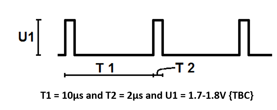
 We are using TMS320F28069. I want to measure pulse ampltude, pulse width and pulse period of the following waveform.  Should I consider using the ADC input pin of this processor. If I use the ADC pin, can be able to capture and compare the waveform?  Are there any suggestions? 

Thanks,

Pradeep.

ALTEN Sweden.

  • Hi Pradeep,

    Pulse amplitude seems the tough part here. As for others you can simply use the eCAP module. Can you give us more details about how varied the pulse amplitude can be?

    Regards,
    Gautam
  • HI Gautam,

    Thanks for the reply. Pulse amplitude will be around 1.8V and with 20% duty cycle.

    Pradeep.
  • The above specs are constants and you need to detect for any variations to detect fault condition, am I right?
    As for amplitude ADC seems the only option wherein ideally you should get 0.36V as resultant ADC input.
  • Yeah, we want to check if there are any fault voltage variations. But it will be tough if the voltage is beyond 3.3V right?
  • Pradeep,

    The below is what I might consider doing, based on what you've mentioned. 

    Bring your input waveform into an ADC pin which is also a COMP+ pin (a pin that has an internal analog comparator's positive input on it).  I'd then configure the device such that the COMP- terminal is controlled by the internal DAC and set to about 1.0V.  The output of this comparator can be output from the C2000 chip via the GPIO mux.  This output will then be a 0 to 3.3V square-wave waveform - with the same characteristic duty cycle and period as the input waveform.

    The COMPOUT GPIO output can then be hardware connected to another GPIO pin - one which has eCAP functionality.  Because the waveform is now 0-3.3V the eCAP can work correctly and perform the job of measuring frequency & duty cycle (as Gautam was mentioning).

    Depending on the minimum duty cycle you expect, you could then have the eCAP trigger an interrupt when it senses a positive edge.  Then, in that interrupt, trigger an ADC sample to occur to try and sense the pulse amplitude.  This may be adequate for you.  Another, less software intensive method of triggering the ADC to sample, might be to have the eCAP GPIO also be configured as External Interrupt 2 (XINT2).  XINT2 can trigger an ADC sample directly if the ADC is configured correctly.

    (PS: note that I haven't tried any of the above in a situation exactly like yours - however, based on my understanding of the peripherals, these might be some things to consider.  Hopefully it helps!)


    Thank you,
    Brett