Other Parts Discussed in Thread: TMS320F28377S
Hi,
I am using lunchpad board with TMS320F28377s. I am initialising the ADCa and just connect it to the potentiometer, and rotate the potentiometer continuously, but the result registry is not continuously changing. it gets fixed values sometimes and it jumps to higher value suddenly. What is wrong here?
it is only changing continuously smaller than 440 and larger than 3896.
Another issue is the zero voltage, when the pin is connected to GND it reads 56. but if I increase the acquisition window (acqps to 100 DEC) it will solve this problem.
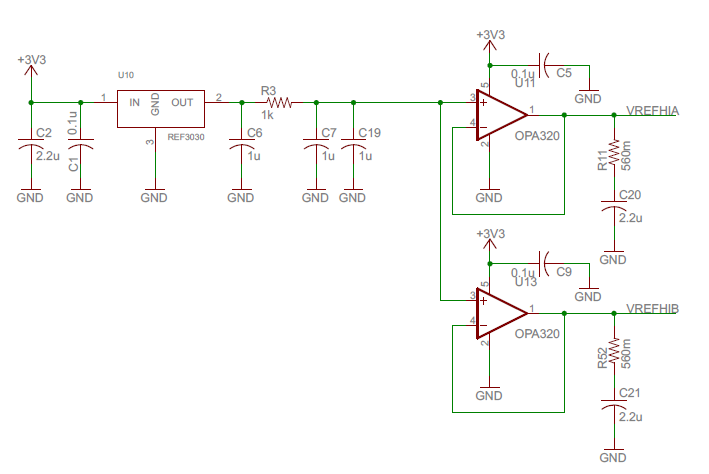
Another Problem, When I power the board with usb, why is the VREFHI 2.99v instead of 3.3v?
void ADC_init(void){
	EALLOW;

	//turn on ADC_A clock
	CpuSysRegs.PCLKCR13.bit.ADC_A = 1;

	//write configurations
	AdcaRegs.ADCCTL2.bit.PRESCALE = 0; //set ADCCLK divider to /1
	AdcSetMode(ADC_ADCA,ADC_RESOLUTION_12BIT,ADC_SIGNALMODE_SINGLE);//ADC_SIGNALMODE_DIFFERENTIAL

	//Set pulse positions to late
	AdcaRegs.ADCCTL1.bit.INTPULSEPOS = 1;	//Interrupt pulse generation occurs at the end of the conversion, 1
											//cycle prior to the ADC result latching into its result register

	//power up the ADC
	AdcaRegs.ADCCTL1.bit.ADCPWDNZ = 1;

	//delay for 1ms to allow ADC time to power up
	delay_us(1000);

	Uint16 acqps;
	//determine minimum acquisition window (in SYSCLKS) based on resolution
	if(ADC_RESOLUTION_12BIT == AdcaRegs.ADCCTL2.bit.RESOLUTION){
		acqps = 14; //75ns
	}
	else { //resolution is 16-bit
		acqps = 63; //320ns
	}

	AdcaRegs.ADCSOC0CTL.bit.CHSEL = 0x04;  		//SOC0 will convert pin ADCIN4 (non-inverting) and ADCIN5 (inverting)
	AdcaRegs.ADCSOC0CTL.bit.ACQPS = acqps; 		//sample window
	AdcaRegs.ADCSOC0CTL.bit.TRIGSEL = 0; 		//trigger only software
	AdcaRegs.ADCINTSEL1N2.bit.INT1SEL = 0; 		//end of SOC0 will set INT1 flag
	AdcaRegs.ADCINTSEL1N2.bit.INT1E = 1;   		//enable INT1 flag at EOC0
	//AdcaRegs.ADCINTSEL1N2.bit.INT1CONT= 1;		//enable continuous mode
	AdcaRegs.ADCINTFLGCLR.bit.ADCINT1 = 1; 		//make sure INT1 flag is cleared

	//AdcaRegs.ADCINTSOCSEL1.bit.SOC0 = 1;		//trigger SOC0 at EOC0

	AdcaRegs.ADCSOCFRC1.bit.SOC0 = 1;			//force the first SOC0


	EDIS;
}
int16_t sampleADC(void){
	int16_t temp;


    //Force start of conversion on SOC0
    AdcaRegs.ADCSOCFRC1.all = 0x01;

    //Wait for end of conversion.
    while(AdcaRegs.ADCINTFLG.bit.ADCINT1 == 0){}  //Wait for ADCINT1
    AdcaRegs.ADCINTFLGCLR.bit.ADCINT1 = 1;        //Clear ADCINT1

    //Get temp sensor sample result from SOC0
    temp = AdcaResultRegs.ADCRESULT0;

    //Return the raw temperature because the devices don't have slope/offset values
    return(temp);

}
void main(void) {
	InitSysCtrl();
	InitPieCtrl();
	IER = 0x0000;
	IFR = 0x0000;
	InitPieVectTable();
	EnableInterrupts();
	hardware_init(); // it is initialising adc and scia

	for (;;){
		int16_t adc = sampleADC();

		transmitDec(INT,adc,1); // sends the adc value to pc
	}

}