


Other Parts Discussed in Thread: TMDSHVBLPFCKIT
Hello,
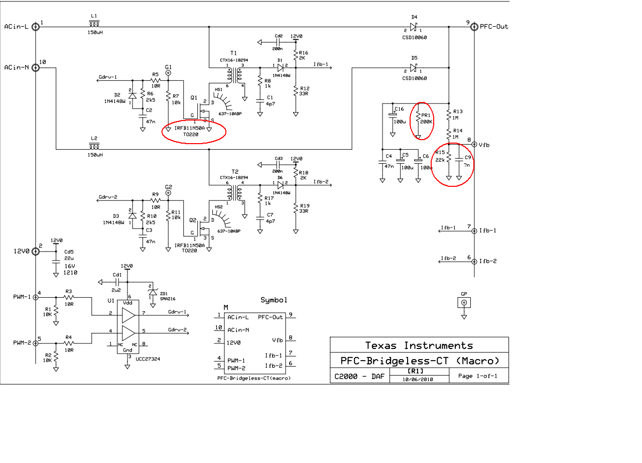
I am designing BLPFC. For that i am referring TI BLPFC (TMDSHVBLPFCKIT) schematics and PFC Bridgeless [R4] Date 31-11 board.
1.In this schematics IRFB11N50A MOSFET used (please see attachment) and actually mounted MOSFET on BLPFC kit is 6R250P GA8806 for
this MOSFET i found IPA60R250CP pdf. The specification of both MOSFET are near about same(not all) so can we substitute IRFB11N50A for
IPA60R250CP.
2.In Vbus feedback circuit voltage divider used as shown in below attachment. In TI BLPFC user guide (Page No.25) wrote that when PFC-OUT=519 Volt then Vfb=3.3 volt Is this resistor configuration correct or not because when i measured vfb for PFC-OUT 95 volt (In build level-1 duty cycle(0.1)) is 0.620 volt.But according to voltage divider with this resistor value i am not getting correct value and also i cant found PR1
resistor on BLPFC kit .Please correct us if there is any wrong.
Thanks in advance...
