This thread has been locked.

If you have a related question, please click the "Ask a related question" button in the top right corner. The newly created question will be automatically linked to this question.

Issues with eCAP module on a TMS320F28335

Other Parts Discussed in Thread: TMS320F28335, CONTROLSUITE

Hi All,

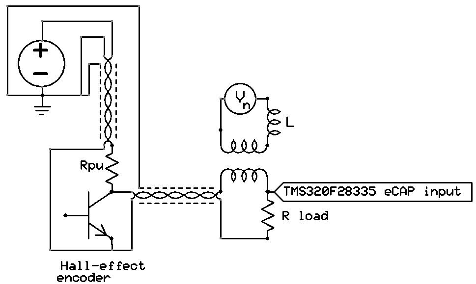
I am looking for some assistance with using the eCAP modules on a TMS320F28335 using Spectrum Digital's eZdsp board. We were having problems with our initial use (detection of transitions of optical encoders for speed estimation), so I wrote a simpler test case to help isolate the problem. The test program continuously buffers data in the 4 registers of one eCAP module. After each capture, an ISR is called to process the data in the current register. Processing consists of accumulating 1000 values and printing the average of the 1000 values on call 1000. Essentially the program is a frequency counter(measuring period) for the input signal. The printing is done directly in the ISR, which is not the best architecture because of the printing time, but it is simple and not responsible for the problems since they occur with or without the printing. No input signal prescaling was used (ECCTL1 bits 13:9 are cleared). I have tried the program with captures of both rising edges and falling edges, and with delta times and absolute times (4 tests). I have also tried all of the possible input qualifications possible. The input for the testing was square waves from 0 to 3 V at a low frequencies around 100 Hz.

There are two problems. First there are sequencing errors. The ISR uses a static variable to keep track of the next register to read: reg 1, reg2, reg3, reg4, reg1, and so on. Sometimes, the sequencing is wrong. That is, the flags provided by the eCAP module to the ISR indicate a different register from next one in the sequence. The second problem is the accuracy of the captures. The frequency of the signal was quite stable based on other measurements, but the period values that were printed varied a lot.

Below is a small excerpt of the output from one of the test cases with delta times.

period = 137853

***ERROR #call 7180, index 3; flags 3; capture: 7528 ALL: 25719 7528 7528 7528

***ERROR #call 7185, index 0; flags 17; capture: 69858 ALL: 69858 69858 74649 354634

***ERROR #call 7190, index 1; flags 17; capture: 53332 ALL: 53332 53332 53332 3459108

***ERROR #call 7195, index 2; flags 3; capture: 70226 ALL: 1303483 70226 70226 70227

***ERROR #call 7200, index 3; flags 9; capture: 42205 ALL: 42205 42205 5499543 42205

period = 129146

period = 123080

***ERROR #call 9205, index 0; flags 17; capture: 7531 ALL: 7531 7531 7531 7144894

period = 127723

***ERROR #call 10210, index 1; flags 9; capture: 7518 ALL: 7518 7518 10243 7518

***ERROR #call 10215, index 2; flags 17; capture: 63551 ALL: 58760 58760 63551 1065067

period = 127000

***ERROR #call 11220, index 3; flags 9; capture: 7525 ALL: 7526 7526 242237 7525

***ERROR #call 11225, index 0; flags 5; capture: 58020 ALL: 58020 569745 58020 58020

***ERROR #call 11230, index 1; flags 9; capture: 59061 ALL: 59061 59061 2574790 59061

period = 137974

***ERROR #call 12235, index 2; flags 3; capture: 7523 ALL: 23934 7523 7523 7523

***ERROR #call 12240, index 3; flags 3; capture: 25338 ALL: 727068 7958 25338 25338

period = 125263

***ERROR #call 13245, index 0; flags 9; capture: 7530 ALL: 7530 7530 19414 7530

***ERROR #call 13250, index 1; flags 3; capture: 58598 ALL: 827327 58598 58598 74707

***ERROR #call 13255, index 2; flags 3; capture: 29337 ALL: 3183281 29337 29337 29337

***ERROR #call 13260, index 3; flags 5; capture: 77109 ALL: 77109 2273121 77109 77109

***ERROR #call 13265, index 0; flags 9; capture: 35364 ALL: 35364 35364 2756127 35364

***ERROR #call 13270, index 1; flags 9; capture: 70414 ALL: 70414 70414 2963684 70414

***ERROR #call 13275, index 2; flags 3; capture: 342 ALL: 2772579 342 342 342

***ERROR #call 13280, index 3; flags 9; capture: 69955 ALL: 69955 69956 1132026 69955

***ERROR #call 13285, index 0; flags 9; capture: 59330 ALL: 59330 59330 4985942 59330

period = 128417

***ERROR #call 14290, index 1; flags 17; capture: 7516 ALL: 7516 7516 7516 9193590

period = 127076

***ERROR #call 15295, index 2; flags 3; capture: 7520 ALL: 8435661 7520 7520 7520

***ERROR #call 15300, index 3; flags 9; capture: 1359 ALL: 12445 12445 2212674 1359

***ERROR #call 15305, index 0; flags 5; capture: 52523 ALL: 52523 2687709 52523 52523

***ERROR #call 15310, index 1; flags 3; capture: 76938 ALL: 1898510 76938 76938 76938

***ERROR #call 15315, index 2; flags 17; capture: 64903 ALL: 64903 64903 64903 5801824

***ERROR #call 15320, index 3; flags 7; capture: 76586 ALL: 1203874 5 76586 76586

***ERROR #call 15325, index 0; flags 17; capture: 63936 ALL: 63936 63936 63936 5571434

As mentioned earlier, the period is an average of 1000 values of a stable signal, so there should be very little variation.

Each time the ISR is called, the eCAP data is validated to ensure that the flags match the expected values. The LSB of the ECFLG register, bit 0, indicates that an interrupt is present, and should always be set when the ISR is called. Bits 1-4 indicate capture events 1-4, respectively have occurred; bit 5 indicates an overflow, and the remainder of the bits are either reserved or used for the PWM functions. A valid flag value should have the INT bit set, the overflow not set, and at least the bit corresponding to the next capture event set. Others may be set if the ISR is not processed quickly enough.

The content of the error message is as follows. After the “***ERROR” prefix, total number of calls to the ISR since the program was started is printed followed by the index of the register that should have data, the flags returned by the eCAP module, the capture data for the register that should have data based on the sequencing of registers so that they would form a circular buffer, and lastly the capture data of all register as they existed at the time. For example, the very last message shows that the error occurred on call number 15325 to the ISR. The data should be in eCAP register 0+1 (capture event 1). Flags show that capture event 4 has occurred. The capture data for the expected event 1 is 63936, and the values in capture register values at that time was 63936, 63936, 63936, and 5571434.

Here are some things I have observed about the errors.

  • The calls are always multiples of 5. If the program is run long enough, there is some offset, but they still occur within a small time interval in multiples of 5.
  • The errors are tightly grouped in time.
  • The flag capture register with the largest value matches the one indicated by the ECFLG register as being the event that occurred.

I would like to know how to get an accurate period measurement and why the errors are occurring and how to handle that issue. There was some variation in the period depending on whether rising edges or falling edges were being detected. Since the controller is socketed on the eZdsp board, I tried a different 28335, and interestingly, the period again changed somewhat. As mentioned before, I tried qualification, and also adding a low-pass filter. Qualification does help to reduce the number of errors with the most giving the best results, although the filter made the problem worse for some reason. The delta measurements had better accuracy than the absolute measurements.

Thanks for any assistance!

Jim Monte

  • Jim,

    First of all, from looking at the errors here you "flags" variable seems to be an accurate predictor of which CAP register holds the incorrect value. Could you breakdown the meaning of this variable for me?

    flags 3 => reg0
    flags 5 => reg1
    flags 9 => reg2
    flags 17 => reg3

    Secondly the sequencing error may be caused by an edge capture that occurs while in the ISR. Then at the end of the ISR this flag is cleared before you record it. This theory explains why the sequence maybe off, but not why it occurs in multiples of five. Could you describe exactly what happens in your ISR? Possibly something else in the ISR causes it to be periodic?

    Regards,

    Cody

  • Hi Cody,

    Thanks for your reply.

    The “flags” variable contains the content of the ECFLG register when the interrupt is called.

    Bit 0 = interrupt occurred

    Bit 1 = event 1 occurred (data in capture register 1)

    Bit 2 = event 2 occurred (data in capture register 2)

    Bit 3 = event 3 occurred (data in capture register 3)

    Bit 4 = event 4 occurred (data in capture register 4)

    Bit 5 = overflow occurred

    The remaining bits either are reserved or applicable to the eCAP's alternate use as a PWM module.

    My index is 0-based, so

    bit 1 set = data in capture reg 1 = my index 0,

    bit 2 set = data in capture reg 2 = my index 1,
    bit 3 set = data in capture reg 3 = my index 2,

    bit 4 set = data in capture reg 4 = my index 3.

    The interrupt bit is always set when the ISR is called. As an example, if only capture register 3 contains data and there is no overflow or unexpected flag set, the ECFLG register has a value of 1 + 1<<3 = 9.

    Aside possibly from the prints every 1000 calls (assuming no errors), the ISR is fast enough relative to the rate that the data is coming that there should not be another edge before it completes. But even if there is, the ECFLG register bit for the interrupt is cleared before additional interrupts are allowed. For example, if capture register 4 contained data and that data was processed in the current ISR call, the sequence is


    /* Clear the events that must be present if no error occurred */

    ECap1Regs.ECCLR.all = ECCLR_CEVT4_CLR | ECCLR_INT_CLR;

    /* Acknowledge this interrupt to receive more interrupts from group 4 */

    PieCtrlRegs.PIEACK.all = PIEACK_GROUP4;


    In the first statement, the macros on the right are defined to set the bits corresponding to clearing event 4 and the interrupt bit.

    The test program including the ISR was written to isolate the problem with the eCAP register, so it is not doing anything besides processing the capture values to get an average period. The average is over 1000 values, which is a multiple of 5, but a relatively large one and there are stretches when the program processes thousands of values without any error. I have append the full ISR below, although it appears that space has been removed from the formatting.

    Jim


    static __interrupt void ecap_isr_run(void)

    {

    /* Keep track of capture being processed */

    static unsigned int index_event = 0;

    unsigned int f_error; /* error codes found */

    volatile unsigned int ecflg;

    unsigned long cap; /* capture values for this call */

    static unsigned int n_call_ok = 0;

    static unsigned long long cap_total = 0;

    static unsigned long n_call_total = 0;

    ecflg = ECap1Regs.ECFLG.all;

    switch (index_event) {

    case 0: /* Event 1 */

    cap = ECap1Regs.CAP1;

    /* Clear the events that must be present if no error occurred */

    ECap1Regs.ECCLR.all = ECCLR_CEVT1_CLR |

    ECCLR_INT_CLR;

    break;

    case 1: /* Event 2 */

    cap = ECap1Regs.CAP2;

    /* Clear the events that must be present if no error occurred */

    ECap1Regs.ECCLR.all = ECCLR_CEVT2_CLR |

    ECCLR_INT_CLR;

    break;

    case 2: /* Event 3 */

    cap = ECap1Regs.CAP3;

    /* Clear the events that must be present if no error occurred */

    ECap1Regs.ECCLR.all = ECCLR_CEVT3_CLR |

    ECCLR_INT_CLR;

    break;

    case 3: /* Event 4 */

    cap = ECap1Regs.CAP4;

    /* Clear the events that must be present if no error occurred */

    ECap1Regs.ECCLR.all = ECCLR_CEVT4_CLR |

    ECCLR_INT_CLR;

    break;

    default:

    (void) fprintf(stderr, "Unexpected event ID %u.\n",

    (unsigned int) index_event);

    } /* end of switch over events */

    /* Test for errors in the returned data */

    ecap_err_check(ecflg, index_event, &f_error);

    /* If an error occurred (including buffer full), log it and start over */

    n_call_total++;

    if (f_error) {

    error_reset();

    (void) fprintf(stderr, "***ERROR #call %lu, index %u; flags %u; "

    " capture: %lu ALL: %lu %lu %lu %lu\n",

    n_call_total, index_event, ecflg, cap,

    ECap1Regs.CAP1,

    ECap1Regs.CAP2,

    ECap1Regs.CAP3,

    ECap1Regs.CAP4);

    n_call_ok = 0;

    }

    else { /* normal case of no error */

    cap_total += cap;

    if (++n_call_ok == 1000) {

    (void) fprintf(stdout, "period = %lu\n", (unsigned long) (cap_total / 1000));

    cap_total = 0;

    n_call_ok = 0; /* reset counter */

    }

    } /* end of case of no error */

    index_event = index_event + 1 & 0x3; /* next index, wrapping after 3 */

    /* Acknowledge this interrupt to receive more interrupts from group 4 */

    PieCtrlRegs.PIEACK.all = PIEACK_GROUP4;

    return;

    } /* end of function ecap_isr_run */


  • Jim,

    I lightly modified your ISR and merged it with a controlSuite example(Example_2823xECap_Capture_Pwm). This file should be attached below. If you add this to the corresponding F28335 example project in controlSuite it should build just fine.

    NOTE:I have added a few if statements to check if I experienced the problems you were talking about, I executed the code for about 20 minutes and did not see any failures.

    First check if index is correct

    "
    if (ECap1Regs.ECFLG.all != 0){        //*********ensure the correct flags were set and cleared by the above case statement.************
     ESTOP0;

    "

    Second check if the values are reasonably close

    "
    CAP1 = ECap1Regs.CAP1;
    CAP2 = ECap1Regs.CAP2;
    CAP3 = ECap1Regs.CAP3;
    CAP4 = ECap1Regs.CAP4;
    if (Preload >=10)             //fill up all cap registers before starting the comparision
     {
     if (CAP4-CAP3>error || CAP4-CAP3<-error){ESTOP0;}   //**************ensure each instantaneous value is with in a reasonable tolerance************
     if (CAP3-CAP2>error || CAP3-CAP2<-error){ESTOP0;}
     if (CAP2-CAP1>error ||CAP2-CAP1<-error){ESTOP0;}
     }
    else
     {Preload++;}
    "

    Hopefully this is a better starting point for you!

    Regards,

    Cody

    //###########################################################################
    // Description:
    //! \addtogroup f2833x_example_list
    //! <h1> eCap capture PWM (ecap_capture_pwm)</h1>
    //!
    //! This example configures ePWM3A for:
    //! - Up count
    //! - Period starts at 2 and goes up to 1000
    //! - Toggle output on PRD
    //!
    //! eCAP1 is configured to capture the time between rising
    //! and falling edge of the ePWM3A output.
    //!
    //! \b External \b Connections \n
    //! - eCap1 is on GPIO24
    //! - ePWM3A is on GPIO4
    //! - Connect GPIO4 to GPIO24.
    //!
    //! \b Watch \b Variables \n
    //! - ECap1IntCount - Successful captures
    //! - ECap1PassCount - Interrupt counts
    //
    //###########################################################################
    // $TI Release: F2833x/F2823x Header Files and Peripheral Examples V141 $
    // $Release Date: November  6, 2015 $
    // $Copyright: Copyright (C) 2007-2015 Texas Instruments Incorporated -
    //             http://www.ti.com/ ALL RIGHTS RESERVED $
    //###########################################################################
    
    #include "DSP28x_Project.h"     // Device Headerfile and Examples Include File
    
    // Configure the start/end period for the timer
    #define PWM3_TIMER_MIN     10
    #define PWM3_TIMER_MAX     8000
    
    // Prototype statements for functions found within this file.
    __interrupt void ecap1_isr(void);
    __interrupt void ecap_isr_run(void);
    void InitECapture(void);
    void InitEPwmTimer(void);
    void Fail(void);
    
    // Global variables used in this example
    Uint32  ECap1IntCount;
    Uint32  ECap1PassCount;
    Uint32  EPwm3TimerDirection;
    
    // To keep track of which way the timer value is moving
    #define EPWM_TIMER_UP   1
    #define EPWM_TIMER_DOWN 0
    
    void main(void)
    {
    // Step 1. Initialize System Control:
    // PLL, WatchDog, enable Peripheral Clocks
    // This example function is found in the DSP2833x_SysCtrl.c file.
       InitSysCtrl();
    
    // Step 2. Initialize GPIO:
    // This example function is found in the DSP2833x_Gpio.c file and
    // illustrates how to set the GPIO to it's default state.
    // InitGpio();  // Skipped for this example
    
       InitEPwm3Gpio();
       InitECap1Gpio();
    
    // Step 3. Clear all interrupts and initialize PIE vector table:
    // Disable CPU interrupts
       DINT;
    
    // Initialize the PIE control registers to their default state.
    // The default state is all PIE interrupts disabled and flags
    // are cleared.
    // This function is found in the DSP2833x_PieCtrl.c file.
       InitPieCtrl();
    
    // Disable CPU interrupts and clear all CPU interrupt flags:
       IER = 0x0000;
       IFR = 0x0000;
    
    // Initialize the PIE vector table with pointers to the shell Interrupt
    // Service Routines (ISR).
    // This will populate the entire table, even if the interrupt
    // is not used in this example.  This is useful for debug purposes.
    // The shell ISR routines are found in DSP2833x_DefaultIsr.c.
    // This function is found in DSP2833x_PieVect.c.
       InitPieVectTable();
    
    // Interrupts that are used in this example are re-mapped to
    // ISR functions found within this file.
       EALLOW;  // This is needed to write to EALLOW protected registers
       PieVectTable.ECAP1_INT = &ecap_isr_run;
       EDIS;    // This is needed to disable write to EALLOW protected registers
    
    // Step 4. Initialize all the Device Peripherals:
    // This function is found in DSP2833x_InitPeripherals.c
    // InitPeripherals();  // Not required for this example
       InitEPwmTimer();    // For this example, only initialize the ePWM Timers
       InitECapture();
    
    // Step 5. User specific code, enable interrupts:
    
    // Initialize counters:
       ECap1IntCount = 0;
       ECap1PassCount = 0;
    
    // Enable CPU INT4 which is connected to ECAP1-4 INT:
       IER |= M_INT4;
    
    // Enable eCAP INTn in the PIE: Group 3 interrupt 1-6
       PieCtrlRegs.PIEIER4.bit.INTx1 = 1;
    
    // Enable global Interrupts and higher priority real-time debug events:
       EINT;   // Enable Global interrupt INTM
       ERTM;   // Enable Global realtime interrupt DBGM
    
    // Step 6. IDLE loop. Just sit and loop forever (optional):
       for(;;)
       {
           __asm("          NOP");
       }
    }
    
    void InitEPwmTimer()
    {
       EALLOW;
       SysCtrlRegs.PCLKCR0.bit.TBCLKSYNC = 0;
    
    
       EPwm3Regs.TBCTL.bit.CTRMODE = TB_COUNT_UP; // Count up
       EPwm3Regs.TBPRD = 0xFFFF;//PWM3_TIMER_MIN;
       EPwm3Regs.TBPHS.all = 0x00000000;
       EPwm3Regs.AQCTLA.bit.PRD = AQ_TOGGLE;      // Toggle on PRD
       EPwm3Regs.TBCTL.bit.CLKDIV = 0x2;//(sysclk/4)
       // TBCLK = SYSCLKOUT
       EPwm3Regs.TBCTL.bit.HSPCLKDIV = 1;
       //EPwm3Regs.TBCTL.bit.CLKDIV = 0;
    
    
       EPwm3TimerDirection = EPWM_TIMER_UP;
    
       EALLOW;
       SysCtrlRegs.PCLKCR0.bit.TBCLKSYNC = 1;
       EDIS;
    }
    
    void InitECapture()
    {
       ECap1Regs.ECEINT.all = 0x0000;             // Disable all capture interrupts
       ECap1Regs.ECCLR.all = 0xFFFF;              // Clear all CAP interrupt flags
       ECap1Regs.ECCTL1.bit.CAPLDEN = 0;          // Disable CAP1-CAP4 register loads
       ECap1Regs.ECCTL2.bit.TSCTRSTOP = 0;        // Make sure the counter is stopped
    
       // Configure peripheral registers
       ECap1Regs.ECCTL2.bit.CONT_ONESHT = 0;      // One-shot
       ECap1Regs.ECCTL2.bit.STOP_WRAP = 3;        // Stop at 4 events
       ECap1Regs.ECCTL1.bit.CAP1POL = 0;          // Falling edge
       ECap1Regs.ECCTL1.bit.CAP2POL = 0;          // Rising edge
       ECap1Regs.ECCTL1.bit.CAP3POL = 0;          // Falling edge
       ECap1Regs.ECCTL1.bit.CAP4POL = 0;          // Rising edge
       ECap1Regs.ECCTL1.bit.CTRRST1 = 1;          // Difference operation
       ECap1Regs.ECCTL1.bit.CTRRST2 = 1;          // Difference operation
       ECap1Regs.ECCTL1.bit.CTRRST3 = 1;          // Difference operation
       ECap1Regs.ECCTL1.bit.CTRRST4 = 1;          // Difference operation
       ECap1Regs.ECCTL2.bit.SYNCI_EN = 1;         // Enable sync in
       ECap1Regs.ECCTL2.bit.SYNCO_SEL = 0;        // Pass through
       ECap1Regs.ECCTL1.bit.CAPLDEN = 1;          // Enable capture units
    
    
       ECap1Regs.ECCTL2.bit.TSCTRSTOP = 1;        // Start Counter
       ECap1Regs.ECCTL2.bit.REARM = 1;            // arm one-shot
       ECap1Regs.ECCTL1.bit.CAPLDEN = 1;          // Enable CAP1-CAP4 register loads
       ECap1Regs.ECEINT.bit.CEVT1 = 1;
       ECap1Regs.ECEINT.bit.CEVT2 = 1;
       ECap1Regs.ECEINT.bit.CEVT3 = 1;
       ECap1Regs.ECEINT.bit.CEVT4 = 1;            // 4 events = interrupt
    }
    
    __interrupt void ecap1_isr(void)
    {
       // Cap input is syc'ed to SYSCLKOUT so there may be
       // a +/- 1 cycle variation
    
       if(ECap1Regs.CAP2 > EPwm3Regs.TBPRD*2+1 || ECap1Regs.CAP2 < EPwm3Regs.TBPRD*2-1)
       {
           Fail();
       }
    
       if(ECap1Regs.CAP3 > EPwm3Regs.TBPRD*2+1 || ECap1Regs.CAP3 < EPwm3Regs.TBPRD*2-1)
       {
           Fail();
       }
    
       if(ECap1Regs.CAP4 > EPwm3Regs.TBPRD*2+1 || ECap1Regs.CAP4 < EPwm3Regs.TBPRD*2-1)
       {
           Fail();
       }
    
       ECap1IntCount++;
    
       if(EPwm3TimerDirection == EPWM_TIMER_UP)
       {
            if(EPwm3Regs.TBPRD < PWM3_TIMER_MAX)
            {
               EPwm3Regs.TBPRD++;
            }
            else
            {
               EPwm3TimerDirection = EPWM_TIMER_DOWN;
               EPwm3Regs.TBPRD--;
            }
       }
       else
       {
            if(EPwm3Regs.TBPRD > PWM3_TIMER_MIN)
            {
               EPwm3Regs.TBPRD--;
            }
            else
            {
               EPwm3TimerDirection = EPWM_TIMER_UP;
               EPwm3Regs.TBPRD++;
            }
       }
    
       ECap1PassCount++;
    
       ECap1Regs.ECCLR.bit.CEVT4 = 1;
       ECap1Regs.ECCLR.bit.INT = 1;
       ECap1Regs.ECCTL2.bit.REARM = 1;
    
       // Acknowledge this interrupt to receive more interrupts from group 4
       PieCtrlRegs.PIEACK.all = PIEACK_GROUP4;
    }
    
    __interrupt void ecap_isr_run(void)
    {
    /* Keep track of capture being processed */
    static unsigned int index_event = 0;
    
    //unsigned int f_error; /* error codes found */
    volatile unsigned int ecflg;
    unsigned long cap; /* capture values for this call */
    
    
    static unsigned int n_call_ok = 0;
    static unsigned long long cap_total = 0;
    static unsigned long n_call_total = 0;
    
    signed long CAP1;
    signed long CAP2;
    signed long CAP3;
    signed long CAP4;
    signed long error = 50;
    static unsigned int Preload = 0;
    ecflg = ECap1Regs.ECFLG.all;
    
    switch (index_event)
    {
    
    	case 0: /* Event 1 */
    
    		cap = ECap1Regs.CAP1;
    
    		/* Clear the events that must be present if no error occurred */
    
    		ECap1Regs.ECCLR.all = 0x02 | 0x01;//ECCLR_CEVT1_CLR | ECCLR_INT_CLR;
    
    		break;
    
    	case 1: /* Event 2 */
    		cap = ECap1Regs.CAP2;
    		/* Clear the events that must be present if no error occurred */
    		ECap1Regs.ECCLR.all = 0x04 | 0x01;//ECCLR_CEVT2_CLR | ECCLR_INT_CLR;
    		break;
    
    	case 2: /* Event 3 */
    
    		cap = ECap1Regs.CAP3;
    		/* Clear the events that must be present if no error occurred */
    		ECap1Regs.ECCLR.all = 0x08 | 0x01;//ECCLR_CEVT3_CLR | ECCLR_INT_CLR;
    		break;
    
    	case 3: /* Event 4 */
    		cap = ECap1Regs.CAP4;
    		/* Clear the events that must be present if no error occurred */
    		ECap1Regs.ECCLR.all = 0x10 | 0x01;//ECCLR_CEVT4_CLR | ECCLR_INT_CLR;
    		break;
    
    	default:
    		//(void) fprintf(stderr, "Unexpected event ID %u.\n",
    		//(unsigned int) index_event);
    		asm(" NOP");
    } /* end of switch over events */
    
    /* Test for errors in the returned data */
    //ecap_err_check(ecflg, index_event, &f_error);
    
    /* If an error occurred (including buffer full), log it and start over */
    n_call_total++;
    
    if (ECap1Regs.ECFLG.all != 0) {								//*********ensure the correct flags were set and cleared by the above case statement.************
    	ESTOP0;
    	//error_reset();
    
    	//(void) fprintf(stderr, "***ERROR #call %lu, index %u; flags %u; "
    	//" capture: %lu ALL: %lu %lu %lu %lu\n",
    	//n_call_total, index_event, ecflg, cap,
    	//ECap1Regs.CAP1,
    	//ECap1Regs.CAP2,
    	//ECap1Regs.CAP3,
    	//ECap1Regs.CAP4);
    	//
    	//
    	//n_call_ok = 0;
    	}
    else
    { /* normal case of no error */
    
    	cap_total += cap;
    
    	if (++n_call_ok == 1000)
    	{
    	//(void) fprintf(stdout, "period = %lu\n", (unsigned long) (cap_total / 1000));
    
    	cap_total = 0;
    	n_call_ok = 0; /* reset counter */
    	}
    } /* end of case of no error */
    
    
    CAP1 = ECap1Regs.CAP1;
    CAP2 = ECap1Regs.CAP2;
    CAP3 = ECap1Regs.CAP3;
    CAP4 = ECap1Regs.CAP4;
    if (Preload >=10)										 		//fill up all cap registers before starting the comparision
    	{
    	if (CAP4-CAP3>error || CAP4-CAP3<-error){ESTOP0;}			//**************ensure each instantaneous value is with in a reasonable tolerance************
    	if (CAP3-CAP2>error || CAP3-CAP2<-error){ESTOP0;}
    	if (CAP2-CAP1>error ||CAP2-CAP1<-error){ESTOP0;}
    	}
    else
    	{Preload++;}


    index_event = index_event + 1 & 0x3; /* next index, wrapping after 3 */
    /* Acknowledge this interrupt to receive more interrupts from group 4 */
    
    PieCtrlRegs.PIEACK.all = PIEACK_GROUP4;
    
    return;


    } /* end of function ecap_isr_run */


    void Fail()
    {
        __asm("   ESTOP0");
    }


    //===========================================================================
    // No more.
    //===========================================================================
    

  • Thanks again. I looked through the program you sent, and there only seems to be two significant difference between it and the one I wrote that is having timing issues: mine does not use the PWM module but instead gets the input from an external signal source, and the SYNCI_EN bit of control register 2 (ECCTL2) is set in yours and not in mine.

    As I understand the eCAP manual, the SYNCI_EN allows the eCAP module to be synchronized with the PWM module that is being used in your program, and when they synchronize, the contents of the phase register CTRPHS is loaded into the time stamp counter register TSCTR. Is that correct? Since this value is used to set the CAP registers it would seem to be giving your program better time alignment. Do you think that difference is causing the timing errors in my version? If so, do you have any idea how I could resolve the issue using an external signal source that does not provide a synchronizing signal?

    I tried to attach the program I wrote with the timing errors and header file that I wrote to define the various eCAP options and a linker file to allow the C run-time files to link properly. The rest of the functions are from the same sample eCAP project as the one you sent. But it seemed like the post did not work because a large block covered the post button after I clicked it and message did not appear after about 30 minutes. So I am trying again without the files. Does something special need to be done to attach files?

    Jim

  • /* Description:
     *
     * eCAP1 is configured to act as a simple frequency counter outputting
     * measured frequency and period whenever it is caught up or every 100
     * updates
     *
     * \b External \b Connections \n
     * - eCap1 is on GPIO24
     *
     */
    
    #include <stdio.h>
    #include "DSP28x_Project.h" /* Device Header file and Examples Include File */
    #include "ecap_control_status_regs.h" 
    
    /* Error codes */
    #define E_COUNTER_OVERFLOW  0x0001 /* timestamp ctr overflowed */
    #define E_BUFFER_FULL       0x0002 /* data buffer full */
    #define E_NO_INTERRUPT      0x0004 /* interrupt flag unset when ISR called */
    #define E_UNEXPECTED_EVENT  0x0008 /* flag set for event not defined */
    #define E_MISSING_CAP1      0x0010 /* capture event 1 expected but not found */
    #define E_MISSING_CAP2      0x0020 /* capture event 2 expected but not found */
    #define E_MISSING_CAP3      0x0040 /* capture event 3 expected but not found */
    #define E_MISSING_CAP4      0x0080 /* capture event 4 expected but not found */


    /* File-scope variables */
    
    static __interrupt void ecap_isr_run(void);
    static void init_ecapture(void);
    static void ecap_err_check(unsigned int flag_info, int index_event,
            unsigned int *p_f_error);
    static void init_system(void);
    //static void print_errors(unsigned int f_error, unsigned int ecflg);
    static void error_reset(void);
    
    
    /***   E N T R Y   P O I N T   ***/
    void main(void)
    {
    
        /* Do initialization */
        init_system();
    
    
        /* Process data that is added to the buffer via the ISR and output
         * period and duty cycle information at fixed intervals */
        for( ; ; ) {
            ;
       } /* end of loop processing data */
    } /* end of function main */


    /* Initialization */
    static void init_system(void)
    {
        /* Initialize System Control:
         *      PLL, WatchDog, enable Peripheral Clocks
         * This example function is found in the DSP2833x_SysCtrl.c file. */
        InitSysCtrl();
    
        /* Initialize GPIO:
         * This example function is found in the DSP2833x_Gpio.c file and
         * illustrates how to set the GPIO to it's default state. */
         /* InitGpio();  -- Skipped for this example */
    
       InitECap1Gpio();
    
        /* Clear all interrupts and initialize PIE vector table:
         *   Disable CPU interrupts */
        DINT;
    
        /* Initialize the PIE control registers to their default state.
         * The default state is all PIE interrupts disabled and flags are cleared.
         * This function is found in the DSP2833x_PieCtrl.c file. */
        InitPieCtrl();
    
        /*Disable CPU interrupts and clear all CPU interrupt flags */
        IER = 0;
        IFR = 0;
    
        /* Initialize the PIE vector table with pointers to the shell Interrupt
         * Service Routines (ISR).
         * This will populate the entire table, even if the interrupt
         * is not used in this example.  This is useful for debug purposes.
         * The shell ISR routines are found in DSP2833x_DefaultIsr.c.
         * This function is found in DSP2833x_PieVect.c. */
       InitPieVectTable();
    
        /* Set initial interrupt service function */
        EALLOW;  /* This is needed to write to EALLOW protected registers */
        PieVectTable.ECAP1_INT = &ecap_isr_run;
        EDIS; /* This is needed to disable write to EALLOW protected registers */
    
        /* InitPeripherals(); -- Not required for this example */
    
        /* Initialize eCAP peripheral */
        init_ecapture();
    
    
        /* Enable CPU INT4 which is connected to ECAP1-4 INT */
        IER |= M_INT4;
    
        /* Enable eCAP INTn in the PIE: Group 3 interrupt 1-6 */
        PieCtrlRegs.PIEIER4.bit.INTx1 = 1;
    
        /* Enable global Interrupts and higher priority real-time debug events */
        EINT; /* Enable Global interrupt INTM */
        ERTM; /* Enable Global realtime interrupt DBGM */
    
        return;
    } /* end of function init_system */


    /* This function sets up the control registers for eCAP module 1 */
    static void init_ecapture()
    { 
        /* Stop the counter by clearing TSCTRSTOP bit (and all others).
         * The example stopped the counter (clearing only that bit) early
         * in the init. There should be no harm in clearing them all (faster)
         * since they will be set up below. */
        ECap1Regs.ECCTL2.all = ECCTL2_TSCTRSTOP_STOP;
    
    
        ECap1Regs.ECCTL1.all =
                ECCTL1_FREE_SOFT_STOP_IMMED | /* stop timer in dbg */
                ECCTL1_PRESCALE_1 | /* scale factor 1 */
                ECCTL1_CAPLDEN_ENABLE | /* enable loading of capture regs
                                         * APPLIES TO BASIC OPERATION. If not
                                         * set, capture values will be 0. */
                ECCTL1_CTRRST4_ENABLE | /* delta for event 4 */
                ECCTL1_CAP4POL_FALLING | /* event 4 is for rising edge */
                ECCTL1_CTRRST3_ENABLE | /* delta for event 3 */
                ECCTL1_CAP3POL_FALLING | /* event 3 is for falling edge */
                ECCTL1_CTRRST2_ENABLE | /* delta for event 2 */
                ECCTL1_CAP2POL_FALLING | /* event 2 is for rising edge */
                ECCTL1_CTRRST1_ENABLE | /* delta for event 1 */
                ECCTL1_CAP1POL_FALLING; /* event 1 is for falling edge */
    
        ECap1Regs.ECCTL2.all =
                ECCTL2_CAP_APWM_CAP | /* capture events (not APWM) */
                ECCTL2_SWSYNC_DISABLE | /* no synch with clock */
                ECCTL2_SWSYNCO_SEL_DISABLE | /* synch not passed to next */
                ECCTL2_SWSYNCI_EN_DISABLE | /* disable sw synch on input */
                ECCTL2_TSCTRSTOP_RUN | /* run the timer */
                ECCTL2_REARM_ENABLE | /* re-arm the trigger
                                       * NOTE: READ BACK AS 0 */
                ECCTL2_STOP_WRAP_4 | /* stop and wrap at event 4 */
                ECCTL2_CONT_ONESHT_CONT; /* continuous mode */
    
        ECap1Regs.ECEINT.all =
                ECEINT_CTROVF_ENABLE | /* interrupt on overflow */
                ECEINT_CEVT4_ENABLE | /* interrupt on event 4 */
                ECEINT_CEVT3_ENABLE | /* interrupt on event 3 */
                ECEINT_CEVT2_ENABLE | /* interrupt on event 2 */
                ECEINT_CEVT1_ENABLE; /* interrupt on event 1 */
    
        /* Clear all defined registers. Note that these are read back as 0s,
         * so checking the register value will show a value of 0 */
        ECap1Regs.ECCLR.all =
                ECCLR_CTR_EQ_CMP_CLR |
                ECCLR_CTR_EQ_PRD_CLR |
                ECCLR_CTROVF_CLR |
                ECCLR_CEVT4_CLR |
                ECCLR_CEVT3_CLR |
                ECCLR_CEVT2_CLR |
                ECCLR_CEVT1_CLR |
                ECCLR_INT_CLR;
        return;
    } /* end of function init_ecapture */


    /* Process normal ISR:
     *      Test for error conditions of either overflow or undefined events
     *      Store data
     */
    static __interrupt void ecap_isr_run(void)
    {
        /* Keep track of capture being processed */
        static unsigned int index_event = 0;
    
        unsigned int f_error; /* error codes found */
        volatile unsigned int ecflg;
        unsigned long cap; /* capture values for this call */
    
        static int n_call_ok = 0;
        static unsigned long long cap_total = 0;
        static unsigned long n_call_total = 0;
    
        ecflg = ECap1Regs.ECFLG.all;
        switch (index_event) {
        case 0: /* Event 1 */
            cap = ECap1Regs.CAP1;
    
            /* Clear the events that must be present if no error occurred */
            ECap1Regs.ECCLR.all = ECCLR_CEVT1_CLR |
                    ECCLR_INT_CLR;
            break;
        case 1: /* Event 2 */
            cap = ECap1Regs.CAP2;
    
            /* Clear the events that must be present if no error occurred */
            ECap1Regs.ECCLR.all = ECCLR_CEVT2_CLR |
                    ECCLR_INT_CLR;
            break;
        case 2: /* Event 3 */
            cap = ECap1Regs.CAP3;
    
            /* Clear the events that must be present if no error occurred */
            ECap1Regs.ECCLR.all = ECCLR_CEVT3_CLR |
                    ECCLR_INT_CLR;
            break;
        case 3: /* Event 4 */
            cap = ECap1Regs.CAP4;
    
            /* Clear the events that must be present if no error occurred */
            ECap1Regs.ECCLR.all = ECCLR_CEVT4_CLR |
                    ECCLR_INT_CLR;
            break;
        default:
            (void) fprintf(stderr, "Unexpected event ID %u.\n",
                    (unsigned int) index_event);
        } /* end of switch over events */
    
    
        /* Test for errors in the returned data */
        ecap_err_check(ecflg, index_event, &f_error);
    
        /* If an error occurred (including buffer full), log it and start over */
        n_call_total++;
        if (f_error) {
            error_reset();
            (void) fprintf(stderr, "***ERROR #call %lu, index %u; flags %u; "
                    " capture: %lu ALL: %lu %lu %lu %lu\n",
                    n_call_total, index_event, ecflg, cap,
                    ECap1Regs.CAP1,
                    ECap1Regs.CAP2,
                    ECap1Regs.CAP3,
                    ECap1Regs.CAP4);
            n_call_ok = 0;
        }
        else { /* normal case of no error */
            cap_total += cap;
            if (++n_call_ok == 1000) {
                (void) fprintf(stdout, "period = %lu\n",
                        (unsigned long) (cap_total / 1000));
                cap_total = 0;
                n_call_ok = 0; /* reset counter */
            }
        } /* end of case of no error */
        index_event = index_event + 1 & 0x3; /* next index, wrapping after 3 */
    
        /* Acknowledge this interrupt to receive more interrupts from group 4 */
        PieCtrlRegs.PIEACK.all = PIEACK_GROUP4;
    
        return;
    } /* end of function ecap_isr_run */


    /* This function checks for errors related to data returned in status
     * registers */
    static void ecap_err_check(unsigned int ecflag, int index_event,
            unsigned int *p_f_error)
    {
        unsigned int f_error; /* error codes found */
        static unsigned int p_event_flag[4] = { /* ID of event */
            ECFLG_CEVT1_TRUE,
            ECFLG_CEVT2_TRUE,
            ECFLG_CEVT3_TRUE,
            ECFLG_CEVT4_TRUE
        };
    
        /* Locate event to process */
        unsigned int event_flag_cur = p_event_flag[index_event];
    
        /* Remove reserved bits since their values are unspecified */
        ecflag &= 0x00FF;
    
        /* Test for overflow */
        if (ecflag & ECFLG_CTROVF_TRUE) { /* overflow */
            f_error = E_COUNTER_OVERFLOW; /* flag error */
            ecflag &= ~ECFLG_CTROVF_TRUE; /* remove from remaining events */
        }
        else { /* no overflow */
            f_error = 0;
        }
    
        /* Test for interrupt. This function should be called only in response
         * to an interrupt, so this bit must be set. */
        if ((ecflag & ECFLG_INT_TRUE) == 0) { /* no interrupt */
            f_error |= E_NO_INTERRUPT; 
        }
        else { /* expected interrupt present */
            ecflag &= ~ECFLG_INT_TRUE; /* clear the bit */
        }
    
        /* There should only be events 1 through 4 remaining in flag_info.
         * There may be more than one if another has started filling. */
        if ((ecflag & ~(ECFLG_CEVT1_TRUE | ECFLG_CEVT2_TRUE | ECFLG_CEVT3_TRUE |
                ECFLG_CEVT4_TRUE)) != 0) {
            f_error |= E_UNEXPECTED_EVENT;
        }
    
        /* If missing capture event A, add to errors */
        if ((ecflag & event_flag_cur) == 0) {
            static unsigned int p_missing_cap[4] = {
                E_MISSING_CAP1,
                E_MISSING_CAP2,
                E_MISSING_CAP3,
                E_MISSING_CAP4
            };
    
            f_error |= p_missing_cap[index_event];
        }
    
    
        *p_f_error = f_error; /* return error info */
    
        return;
    } /* end of function ecap_err_check */


    /* Reset capturing on error */
    static void error_reset(void)
    {
        /* Clear all events */
        ECap1Regs.ECCLR.all =
                ECFRC_CTR_EQ_CMP_SET |
                ECFRC_CTR_EQ_PRD_SET |
                ECFRC_CTROVF_SET;
    
        /* Reset capturing */
       //Cap1Regs.ECCTL2.bit.REARM = ECCTL2_REARM_ENABLE_BIT_VAL;
    
        return;
    } /* end of function error_reset */


  • The linker command file seemed to be the problem. Perhaps its .cmd extension flagged it as a potentially malicious Windows batch file. Here it is again as a 7-28335_RAM_lnk_combined.7z.datzip file with a .dat extension.

  • I'm glad you got the files to upload, .cmd files are commonly blocked so that was most likely the issue. Answers to your questions below:
    1. Yes, on a sync event CTRPHS is loaded into TSCTR.
    2. I don't think the sync event will help much if at all with the accuracy, ill *try* to run an experiment this afternoon to confirm if this is true.

    Can you toggle a GPIO at the beginning and end of your ISR? Measure the time between these pulses to see how long the ISR takes to execute. Then run this again after removing the print statements, how much faster is it?

    Just an aside why are you not using the eQEP module?

    Regards,
    Cody
  • Based on past experience, I know that the prints are very slow. The "real" program does not have anything like them to slow the ISR call, but still had the issues seen in this test program. I do not think I will have an opportunity to run your test with the GPIO toggle for at least another day, but I will try it as soon as I can. It would be interesting to know just low long the prints are taking. I suspect the time will be quite variable and depend a little even on the values being printed since they are converted from binary to ASCII. Another thing I will try that will make a better test is to just buffer the data in the ISR and then do the output after the buffer is full to remove the issue with printing in an ISR.

    We have three Hall-effect sensors that are 120 degrees apart in phase, so the eQEP module does not do what we need.

    Jim
  • I wrote the test without any printing in the ISR and the eCAP values were perfect when I printed them out at the end of the test. So the print calls were to blame? No. I ran the test again where the board is usually operated, and the results were as bad as ever. It turns out that there is an EMI issue that has been affecting the results. Thanks everyone who looked at my question, especially Cody. I will not mark this question as answered quite yet and will  update regarding the EMI when we find out more about it to hopefully help out anyone else who encounters something similar.

    Jim

    /* Description:
     *
     * eCAP1 is configured to act as a simple frequency counter outputting
     * measured frequency and period whenever it is caught up or every 100
     * updates
     *
     * \b External \b Connections \n
     * - eCap1 is on GPIO24
     *
     */
    
    #include <stdio.h>
    #include "DSP28x_Project.h" /* Device Header file and Examples Include File */
    #include "ecap_control_status_regs.h" 
    
    /* Error codes */
    #define E_COUNTER_OVERFLOW  0x0001 /* timestamp ctr overflowed */
    #define E_BUFFER_FULL       0x0002 /* data buffer full */
    #define E_NO_INTERRUPT      0x0004 /* interrupt flag unset when ISR called */
    #define E_UNEXPECTED_EVENT  0x0008 /* flag set for event not defined */
    #define E_MISSING_CAP1      0x0010 /* capture event 1 expected but not found */
    #define E_MISSING_CAP2      0x0020 /* capture event 2 expected but not found */
    #define E_MISSING_CAP3      0x0040 /* capture event 3 expected but not found */
    #define E_MISSING_CAP4      0x0080 /* capture event 4 expected but not found */
    
    /* Size of data buffer. Enforce even size to avoid issues with matching
     * the size when aligning to 2 byte boundary */
    #define N_BYTE_DATA_BUF     1000 /* # 16-bit bytes for errors/periods */
    #if N_BYTE_DATA_BUF % 2
    #error "Buffer size must be a multiple of 2"
    #endif
    
    #define N_ISR_CALL_MAX      100000 /* maximum length of test in ISR calls */
    
    /* File-scope variables */
    /* Data buffer. Format:                 Offset
     *      Int32 index of call                 0   (2 Byte total)
     *          If error, negated
     *
     *      if period
     *          Uint32 period value             2   (2 B, 4 B total)
     *      if error
     *          Uint32[4] cap1, cap2, cap3,
     *          cap4 values                     2   (8 B, 10 B total)
     *          Uint16 cap index value         10   (1 B, 11 B total)
     *          Uint16 flags value             11   (1 B, 12 B total)
     */
    
    static Uint32 p_data[N_BYTE_DATA_BUF / 2];
    static char *p_data_cur; /* current position in buffer */
    static char *p_data_end; /* byte past last position in buffer */
    
    static __interrupt void ecap_isr_run(void);
    static void init_ecapture(void);
    static void ecap_err_check(unsigned int flag_info, int index_event,
            unsigned int *p_f_error);
    static void init_system(void);
    static void error_reset(void);
    static int buffer_period(Uint32 n_call_total, Uint32 period);
    static int buffer_error(Uint32 n_call_total, Uint16 index_event,
            Uint16 ecflg, Uint32 *p_cap);
    static void print_data(void);
    
    
    /***   E N T R Y   P O I N T   ***/
    void main(void)
    {
        /* Init data buffer variables */
        p_data_cur = (char *) p_data;
        p_data_end = (char *) p_data + N_BYTE_DATA_BUF; /* 16-bit bytes */
    
        /* Do initialization */
        init_system();
    
    
        /* Process data that is added to the buffer via the ISR and output
         * period and duty cycle information at fixed intervals */
        for( ; ; ) {
            ;
       } /* end of loop processing data */
    } /* end of function main */


    /* Initialization */
    static void init_system(void)
    {
        /* Initialize System Control:
         *      PLL, WatchDog, enable Peripheral Clocks
         * This example function is found in the DSP2833x_SysCtrl.c file. */
        InitSysCtrl();
    
        /* Initialize GPIO:
         * This example function is found in the DSP2833x_Gpio.c file and
         * illustrates how to set the GPIO to it's default state. */
         /* InitGpio();  -- Skipped for this example */
    
       InitECap1Gpio();
    
        /* Clear all interrupts and initialize PIE vector table:
         *   Disable CPU interrupts */
        DINT;
    
        /* Initialize the PIE control registers to their default state.
         * The default state is all PIE interrupts disabled and flags are cleared.
         * This function is found in the DSP2833x_PieCtrl.c file. */
        InitPieCtrl();
    
        /*Disable CPU interrupts and clear all CPU interrupt flags */
        IER = 0;
        IFR = 0;
    
        /* Initialize the PIE vector table with pointers to the shell Interrupt
         * Service Routines (ISR).
         * This will populate the entire table, even if the interrupt
         * is not used in this example.  This is useful for debug purposes.
         * The shell ISR routines are found in DSP2833x_DefaultIsr.c.
         * This function is found in DSP2833x_PieVect.c. */
       InitPieVectTable();
    
        /* Set initial interrupt service function */
        EALLOW;  /* This is needed to write to EALLOW protected registers */
        PieVectTable.ECAP1_INT = &ecap_isr_run;
        EDIS; /* This is needed to disable write to EALLOW protected registers */
    
        /* InitPeripherals(); -- Not required for this example */
    
        /* Initialize eCAP peripheral */
        init_ecapture();
    
    
        /* Enable CPU INT4 which is connected to ECAP1-4 INT */
        IER |= M_INT4;
    
        /* Enable eCAP INTn in the PIE: Group 3 interrupt 1-6 */
        PieCtrlRegs.PIEIER4.bit.INTx1 = 1;
    
        /* Enable global Interrupts and higher priority real-time debug events */
        EINT; /* Enable Global interrupt INTM */
        ERTM; /* Enable Global realtime interrupt DBGM */
    
        return;
    } /* end of function init_system */


    /* This function sets up the control registers for eCAP module 1 */
    static void init_ecapture()
    { 
        /* Stop the counter by clearing TSCTRSTOP bit (and all others).
         * The example stopped the counter (clearing only that bit) early
         * in the init. There should be no harm in clearing them all (faster)
         * since they will be set up below. */
        ECap1Regs.ECCTL2.all = ECCTL2_TSCTRSTOP_STOP;
    
    
        ECap1Regs.ECCTL1.all =
                ECCTL1_FREE_SOFT_STOP_IMMED | /* stop timer in dbg */
                ECCTL1_PRESCALE_1 | /* scale factor 1 */
                ECCTL1_CAPLDEN_ENABLE | /* enable loading of capture regs
                                         * APPLIES TO BASIC OPERATION. If not
                                         * set, capture values will be 0. */
                ECCTL1_CTRRST4_ENABLE | /* delta for event 4 */
                ECCTL1_CAP4POL_FALLING | /* event 4 is for rising edge */
                ECCTL1_CTRRST3_ENABLE | /* delta for event 3 */
                ECCTL1_CAP3POL_FALLING | /* event 3 is for falling edge */
                ECCTL1_CTRRST2_ENABLE | /* delta for event 2 */
                ECCTL1_CAP2POL_FALLING | /* event 2 is for rising edge */
                ECCTL1_CTRRST1_ENABLE | /* delta for event 1 */
                ECCTL1_CAP1POL_FALLING; /* event 1 is for falling edge */
    
        ECap1Regs.ECCTL2.all =
                ECCTL2_CAP_APWM_CAP | /* capture events (not APWM) */
                ECCTL2_SWSYNC_DISABLE | /* no synch with clock */
                ECCTL2_SWSYNCO_SEL_DISABLE | /* synch not passed to next */
                ECCTL2_SWSYNCI_EN_DISABLE | /* disable sw synch on input */
                ECCTL2_TSCTRSTOP_RUN | /* run the timer */
                ECCTL2_REARM_ENABLE | /* re-arm the trigger
                                       * NOTE: READ BACK AS 0 */
                ECCTL2_STOP_WRAP_4 | /* stop and wrap at event 4 */
                ECCTL2_CONT_ONESHT_CONT; /* continuous mode */
    
        ECap1Regs.ECEINT.all =
                ECEINT_CTROVF_ENABLE | /* interrupt on overflow */
                ECEINT_CEVT4_ENABLE | /* interrupt on event 4 */
                ECEINT_CEVT3_ENABLE | /* interrupt on event 3 */
                ECEINT_CEVT2_ENABLE | /* interrupt on event 2 */
                ECEINT_CEVT1_ENABLE; /* interrupt on event 1 */
    
        /* Clear all defined registers. Note that these are read back as 0s,
         * so checking the register value will show a value of 0 */
        ECap1Regs.ECCLR.all =
                ECCLR_CTR_EQ_CMP_CLR |
                ECCLR_CTR_EQ_PRD_CLR |
                ECCLR_CTROVF_CLR |
                ECCLR_CEVT4_CLR |
                ECCLR_CEVT3_CLR |
                ECCLR_CEVT2_CLR |
                ECCLR_CEVT1_CLR |
                ECCLR_INT_CLR;
        return;
    } /* end of function init_ecapture */


    /* Process normal ISR:
     *      Test for error conditions of either overflow or undefined events
     *      Store data
     */
    static __interrupt void ecap_isr_run(void)
    {
        /* Keep track of capture being processed */
        static unsigned int index_event = 0;
    
        unsigned int f_error; /* error codes found */
        volatile unsigned int ecflg;
        unsigned long cap; /* capture values for this call */
    	unsigned long p_cap[4]; /* array of cap values */
    
        static int n_call_ok = 0;
        static unsigned long long cap_total = 0;
        static unsigned long n_call_total = 0;
        static int f_test_done = 0;
    
        /* Values to clear appropriate flags */
        static const int p_flag_clear[] = {
            ECCLR_CEVT1_CLR | ECCLR_INT_CLR,
            ECCLR_CEVT2_CLR | ECCLR_INT_CLR,
            ECCLR_CEVT3_CLR | ECCLR_INT_CLR,
            ECCLR_CEVT4_CLR | ECCLR_INT_CLR
        };
    
    
        /* If test is done, just exit */
        if (f_test_done) {
            return;
        }
    
        /* Save flags and cap value */
        ecflg = ECap1Regs.ECFLG.all;
        cap = (&ECap1Regs.CAP1)[index_event];
        p_cap[0] = ECap1Regs.CAP1;
        p_cap[1] = ECap1Regs.CAP2;
        p_cap[2] = ECap1Regs.CAP3;
        p_cap[3] = ECap1Regs.CAP4;
    
        /* Clear flags */
        ECap1Regs.ECCLR.all = p_flag_clear[index_event];
    
        /* Test for errors in the returned data */
        ecap_err_check(ecflg, index_event, &f_error);
    
        /* If an error occurred (including buffer full), log it and start over */
        n_call_total++;
        if (f_error) {
            error_reset();
            if (buffer_error(n_call_total, index_event, ecflg, p_cap)) {
                print_data(); /* output results */
                f_test_done = 1; /* terminate data acquisition */
            }
        //    (void) fprintf(stderr, "***ERROR #call %lu, index %u; flags %u; "
        //            " capture: %lu ALL: %lu %lu %lu %lu\n",
        //            n_call_total, index_event, ecflg, cap,
        //            ECap1Regs.CAP1,
        //            ECap1Regs.CAP2,
        //            ECap1Regs.CAP3,
        //            ECap1Regs.CAP4);
            n_call_ok = 0;
        }
        else { /* normal case of no error */
            cap_total += cap;
            if (++n_call_ok == 1000) {
                /* Save data for period */
                if (buffer_period(n_call_total, (Uint32) (cap_total / 1000))) {
                    print_data(); /* output results */
                    f_test_done = 1; /* terminate data acquisition */
                }
    
               // (void) fprintf(stdout, "period = %lu\n",
               //     (unsigned long) (cap_total / 1000));
                cap_total = 0;
                n_call_ok = 0; /* reset counter */
            }
        } /* end of case of no error */
        index_event = index_event + 1 & 0x3; /* next index, wrapping after 3 */
    
        /* Test for end due to enough calls to ISR */
        if (n_call_total == N_ISR_CALL_MAX) {
            print_data(); /* output results */
            f_test_done = 1; /* terminate data acquisition */
        }
    
    
        /* Acknowledge this interrupt to receive more interrupts from group 4 */
        PieCtrlRegs.PIEACK.all = PIEACK_GROUP4;
    
        return;
    } /* end of function ecap_isr_run */


    /* This function checks for errors related to data returned in status
     * registers */
    static void ecap_err_check(unsigned int ecflag, int index_event,
            unsigned int *p_f_error)
    {
        unsigned int f_error; /* error codes found */
        static unsigned int p_event_flag[4] = { /* ID of event */
            ECFLG_CEVT1_TRUE,
            ECFLG_CEVT2_TRUE,
            ECFLG_CEVT3_TRUE,
            ECFLG_CEVT4_TRUE
        };
    
        /* Locate event to process */
        unsigned int event_flag_cur = p_event_flag[index_event];
    
        /* Remove reserved bits 15:8 since their values are unspecified */
        ecflag &= 0x00FF;
    
        /* Test for overflow */
        if (ecflag & ECFLG_CTROVF_TRUE) { /* overflow */
            f_error = E_COUNTER_OVERFLOW; /* flag error */
            ecflag &= ~ECFLG_CTROVF_TRUE; /* remove from remaining events */
        }
        else { /* no overflow */
            f_error = 0;
        }
    
        /* Test for interrupt. This function should be called only in response
         * to an interrupt, so this bit must be set. */
        if ((ecflag & ECFLG_INT_TRUE) == 0) { /* no interrupt */
            f_error |= E_NO_INTERRUPT; 
        }
        else { /* expected interrupt present */
            ecflag &= ~ECFLG_INT_TRUE; /* clear the bit */
        }
    
        /* There should only be events 1 through 4 remaining in flag_info.
         * There may be more than one if another has started filling. */
        if ((ecflag & ~(ECFLG_CEVT1_TRUE | ECFLG_CEVT2_TRUE | ECFLG_CEVT3_TRUE |
                ECFLG_CEVT4_TRUE)) != 0) {
            f_error |= E_UNEXPECTED_EVENT;
        }
    
        /* If missing capture event for this index, add to errors */
        if ((ecflag & event_flag_cur) == 0) {
            static unsigned int p_missing_cap[4] = {
                E_MISSING_CAP1,
                E_MISSING_CAP2,
                E_MISSING_CAP3,
                E_MISSING_CAP4
            };
    
            f_error |= p_missing_cap[index_event];
        }
    
    
        *p_f_error = f_error; /* return error info */
    
        return;
    } /* end of function ecap_err_check */


    /* Reset capturing on error */
    static void error_reset(void)
    {
        /* Clear all events */
        ECap1Regs.ECCLR.all =
                ECFRC_CTR_EQ_CMP_SET |
                ECFRC_CTR_EQ_PRD_SET |
                ECFRC_CTROVF_SET;
    
        /* Reset capturing */
       //Cap1Regs.ECCTL2.bit.REARM = ECCTL2_REARM_ENABLE_BIT_VAL;
    
        return;
    } /* end of function error_reset */


    /* Write error data into buffer.
     *
     * Return 0 if buffered ok; +1 if error */
    static int buffer_error(Uint32 n_call_total, Uint16 index_event,
            Uint16 ecflg, Uint32 *p_cap)
    {
        /* Test for full buffer */
        if (p_data_cur + 12 > p_data_end) {
            return +1;
        }
    
        /* Write error at current location */
        *((int32 *) p_data_cur) = -n_call_total;
        p_data_cur += 2;
        *((Uint32 *) p_data_cur) = p_cap[0];
        p_data_cur += 2;
        *((Uint32 *) p_data_cur) = p_cap[1];
        p_data_cur += 2;
        *((Uint32 *) p_data_cur) = p_cap[2];
        p_data_cur += 2;
        *((Uint32 *) p_data_cur) = p_cap[3];
        p_data_cur += 2;
        *((Uint16 *) p_data_cur) = index_event;
        p_data_cur++;
        *((Uint16 *) p_data_cur) = ecflg;
        p_data_cur++;
    
        return 0;
    } /* end of function buffer_error */


    /* Write period data into buffer
     *
     * Return 0 if buffered ok; +1 if error */
    static int buffer_period(Uint32 n_call_total, Uint32 period)
    {
        /* Test for full buffer */
        if (p_data_cur + 4 > p_data_end) {
            return +1;
        }
    
        /* Write error at current location */
        *((Uint32 *) p_data_cur) = n_call_total;
        p_data_cur += 2;
        *((Uint32 *) p_data_cur) = period;
        p_data_cur += 2;
    
        return 0;
    } /* end of function buffer_period */


    /* Output results */
    static void print_data(void)
    {
        char *p_buf_cur = (char *) p_data;
        char *p_buf_end = p_data_cur;
    
        /* Print each result until reach end of data */
        while (p_buf_cur < p_buf_end) {
            int32 index_call = *(int32 *) p_buf_cur;
    
            /* Identify period/error message */
            if (index_call < 0) { /* error */
                Uint16 index_cap;
                Uint16 flag;
                Uint32 p_cap[4];
                Uint32 cap;
    
                /* Access values from buffer */
                p_cap[0] = *(Uint32 *) (p_buf_cur + 2);
                p_cap[1] = *(Uint32 *) (p_buf_cur + 4);
                p_cap[2] = *(Uint32 *) (p_buf_cur + 6);
                p_cap[3] = *(Uint32 *) (p_buf_cur + 8);
                index_cap = *((Uint16 *) (p_buf_cur + 10));
                flag = *((Uint16 *) (p_buf_cur + 11));
    
                cap = p_cap[index_cap];
                index_call = -index_call;
    
                (void) fprintf(stdout, "***ERROR call # %ld;index=%u;"
                        "flags %u;capture:%lu ALL:%lu %lu %lu %lu\n",
                        index_call, index_cap, flag, cap,
                        p_cap[0], p_cap[1], p_cap[2], p_cap[3]);
                p_buf_cur += 12; /* step to next record */
    
            }
            else { /* Period */
                Uint32 period = *(Uint32 *) (p_buf_cur + 2);
                (void) fprintf(stdout, "call # %lu; period = %lu\n",
                		index_call, period);
                p_buf_cur += 4;
            }
        } /* end of loop over data */
    
        return;
    } /* end of fucntion print_data */


  • There is some HVAC equipment outside of the room where the testing is done -- 4 compressors and 4 large fans. They seem to be the culprit, but unfortunately they run almost constantly to some extent, e.g., one or more compressors and one or more fans. During the rare times when everything is off, the errors go away. So far we have added shielded wires from the optical encoders to the eCAP module inputs. There was a substantial improvement, but not enough. The most severe errors, discrepancies between the expected flags and actual flags when an interrupt occurs, have been eliminated by the shielding. But false triggers still are occurring. These show themselves as shorter than normal periods. We have tried median filtering in our application, but sometimes the errors occur in long enough bursts to make this approach an improvement but not a complete solution for a filter length of a usable size.

    Jim
  • Hi Jim,

    I have a few thoughts, based mainly on your last post:
    1) Many hall-effect sensors require a pull-up resistor in order to work.  Are you doing this - assuming they are needed?  If needed, are the pull-ups adequately strong? 
    2) You mentioned that you had experimented with the GPIO qualification.  Keep in mind that you can also change the 'sampling period' by editing the GP*CTRL registers if you desire.  Obviously if you go too high, you may start effecting the control loop.


    Thank you,
    Brett

  • Hi Brett,

    Thanks for your reply. The encoders are Hall-effect sensors as I had written earlier but not in my last post. Yes, they do require pull-up resistors, and we are using a value suggested by the manufacturer of the encoder (10k), although we could use a somewhat lower value. The person I talked to was not 100% sure of the identification of our encoder, so I wanted to use a safe value. I had seen the ability to change the sampling period, but would like to avoid that if possible since the top speed could be quite high.

    Thinking about your reply did give me another idea. The noise from the compressors and fans is probably being magnetically coupled to the signal with a very loose coupling. So a little current flow could severely attenuate the noise without much effect on the signal. If the input impedance to the eCAP module were lowered, the noise voltage would hopefully be reduced to negligible levels. I am considering making a voltage divider by adding a resistor from the eCAP input to ground so current will always flow. The sensor is rated for up to 24 V, so there is plenty of margin for making up the lost voltage.

    Jim

  • Hi Jim,

    Can you suggest me, "static __interrupt void ecap_isr_run(void)" loop how executed in-side the program code and what is the use of "ecap_isr_run" on "PieVectTable.ECAP1_INT" initialization.
  • Hi Asim,

    ecap_isr_run() is the function that is called whenever there is an interrupt due to an eCAP event. It is set as the callback function in the PieVectTable.ECAP1_INT statement.

    Jim

  • We seem to have resolved the EMI issue. First we added a line filter to reduce the amount of EMI entering from equipment.This change resulted in a noticeable improvement in the eCAP results but still some errors remained. Then we added the resistor shown as R load in the figure below and raised the supply voltage to provide the original 3.3 volts to the eCAP input at a logic HIGH value. This new resistor had two effects. First it divided any noise voltage that gets into the circuit between the pull-up resistor and itself. They were both 7.5k, so that cut the noise in half. At the same time the signal voltage at the eCAP input remained at 3.3 V due to the higher supply voltage. More importantly, the current drawn by R load at a logic HIGH level reduced the amount of noise voltage coming into the circuit by causing it to drop across the impedance shown as L. Thanks everyone for your suggestions and help.

    Jim

  •  Sorry everyone, the nice figure I made and pasted into the reply did not get included. Hopefully this time it works better as an attachment.

  • Hi Jim,

    I'm glad you were able to get a working system.  Thank you for sharing what you found.


    Thank you,
    Brett