This thread has been locked.

If you have a related question, please click the "Ask a related question" button in the top right corner. The newly created question will be automatically linked to this question.

No source available for "0x3ff9ce", Device is held in Reset

Other Parts Discussed in Thread: TMS320F28335

I've searched on these two (2) topics:

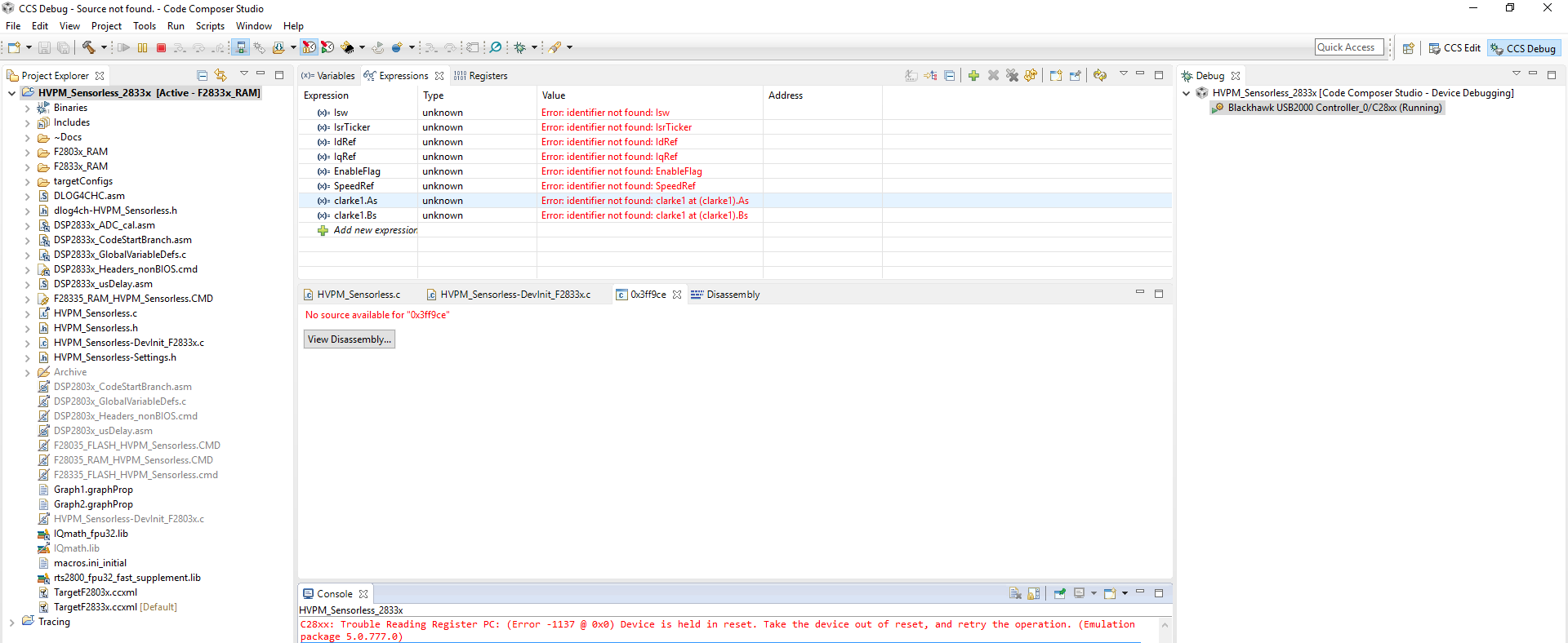
1) No source available for "0x3ff9ce"

2) Device is held in Reset

To mitigate the first, I hit the Play button while in Debug mode and also enabled Real-time mode prior to that, accepting the dialog box that occurs when enabling.  The second topic, concerning Reset, seems to point towards a failed F28335 chip.  The "Test Connection" feature of CCSv6.1 passes.

Any ideas on how to get communication by getting the device out of Reset?

  • Hi Tim,

    As for your first query of "No source available" you can refer this thread:
    e2e.ti.com/.../252845

    For your 2nd query, which board is this? Check the boot pins and other switch configurations.

    Regards,
    Gautam
  • The board is a Semikron SKAI2-LV, which has a TMS320F28335 MCU acting in concert with a FPGA (continuous monitoring of faults and fault conditions, termed the LCU).  There is a boot sequence, which requires GPIO79 to start LOW and go HIGH once the F28335 is ready.  That stated, I don't think I'm getting to that point in the code...I don't think I'm getting anywhere in the code.  I've read the post before for the link you gave me, but thank you anyway for confirming that I was on the right track.  The Semikron SKAI2-LV does normally boot from a Flash-chip, which can be programmed using a CANpro device.  As I'm trying to debug this setup, I figured it would be better to use the JTAG connection to the MCU.

    I'm going to try to use the F28335 DIMM-type prototype card that is used in the TI kits, and see if I can get that to function, but that is about a week out as I wait for it to ship to me.  I'm hoping that there are some tools in CCSv6.1 that might help me to diagnose what is going on.  The F28335 on the board is BGA, so getting to the pins for a measurement is impossible.

    Any suggestions to get this functional are appreciated.

  • Hi Tim, Is this issue resolved?

    Regards,

    Vivek Singh
  • Vivek,
    Checking the device through Semikron to ensure this issue is not hardware related before proceeding further. Thank you for your patience in this matter as the device is traveling from the US to Germany and back again over a month's-plus timeframe.
    -Tim
  • Vivek et al,
    I tried to get a less complex set of code functional, and in the process found that the boot mode settings for the TMS320F28335 that is on this board are not set to allow the code to be loaded out of SARAM. As such, I have modified my code to allow for the program to be loaded out of FLASH, and this solved my problem of communication and the program kicked off. Thank you again!
    -Tim
  • Vivek et al,

    After successfully programming my device by loading a small program into FLASH to simply blink a pair of LEDs (so I know the device is functional), I attempted to program the HVPM_Sensorless_2833x into FLASH. This example continues to give me an issue. I have followed Section 3.4 of SPRCA73 to execute the example from FLASH, though, I have utilized the F28335_FLASH_HVPM_Sensorless.cmd file as opposed to the F28335.cmd file stated in the SPRCA73 document. I have added the DSP2833x_CSMPasswords.asm per this document as well. When I added the DSP2833x_MemCopy.c file to the project, it caused errors as it was already defined - so it was excluded from the build. Finally, as I could not figure out where to define "FLASH" in the compiler (should it be in Show Build Settings -> Build->C2000 Compiler->Advanced Options->Predefined Symbols in the Pre-defined NAME area?), I simply removed the #ifdef and #endif statements for the FLASH section, leaving the code to always execute the MemCopy and InitFlash functions, along with #pragma CODE_SECTION(xxx,"ramfuncs"), where "xxx" is Initflash, MainISR, and OffsetISR - each with their own line at the beginning of HVPM_Sensorless.c. I found out this past week that the Semikron SKAI2-LV (device I'm using) has its Boot Loader setup to boot to FLASH 0x33fff6 (GPIO87:GPIO84=XA15:XA12=0x1111) when the CAN_BMS (X20:03) pin is pulled LOW or in a FLOAT state.

    When I run the LED-blinker out of FLASH, the debugger sends it to FLASH once the debugger is started. For the HVPM_Sensorless_2833x example, however, it does not do this. Am I missing something critical in the compiler as part of this setup?

    From what I can tell, the *.cmd files are nearly identical between the two projects. The HVPM_Sensorless_DevInit_F2833x.c file is much more complex, starting the GPIO configuration earlier than the LED blinker. Could this be an issue?

    I'm on the road towards success at this point. I know I have a functional board/chip and I can program something simple. I really need the HVPM_Sensorless_F2833x example to work before I start to modify and update it with some added features. Any help is greatly appreciated.
    -Tim
  • Thank you all for your help with this topic. To this day, I cannot get the HVPM_Sensorless_2833x to load into FLASH. My fix has been to use the program that I was able to load into FLASH (the LED blinker) and then simply copy over the core of the HVPM_Sensorless_2833x code. That has worked for me to be able to compile and debug the system.