This thread has been locked.
If you have a related question, please click the "Ask a related question" button in the top right corner. The newly created question will be automatically linked to this question.
I am working on a controller for a phase shift controlled converter. I need to implement a start up procedure to safely bring up the output voltage without blowing up the FETs. There are two possible ways for the start up to be done; either a simple 10 percent duty cycle PWM type signal or an open loop phase shift modulated output. Once the output is in a known state I would then like to switch over to the closed loop phase shift modulator operation. My first attempt was to try the PWM method, but unfortunately it looks like the ePWM modules are not reconfiguring in real time. Any ideas?
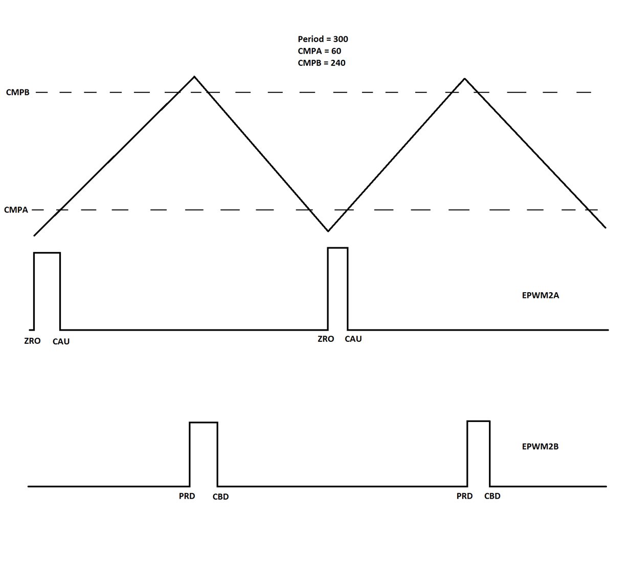
I've also been having a little trouble with my start up routine and I'm not sure what the problem is. I try to get the ePWMxA channel to put out a 1us pulse every 10us as noted previously. I also try to get the same thing on the corresponding ePWMxB channel with a 5us offset.
In practice however I am not getting anything on the ePWMxB channel. It just stays off and does nothing. I have a 60MHz clock speed and I set the period to be 600 counts long. I looked at the registers while debugging and I get the period in updown count mode to be 300 counts and the CMPA = 60 and CMPB =240. I even see the TBCTR register hitting 300 so I know it is counting up and down. I'm at a loss to understand why this is happening.
I wrote the following code to set up the ePWM channel described above.
#include "PeripheralHeaderIncludes.h"
#include "DSP2803x_EPWM_defines.h" // useful defines specific to EPWM
extern volatile struct EPWM_REGS *ePWM[];
//---------------------------------------------------------------------------
void DAB_STARTUP_PWM_CNF(int16 n, int16 Period)
{
// n = the ePWM module number, i.e. selects the target module for init.
(*ePWM[n]).TBCTL.bit.PRDLD = TB_IMMEDIATE; // set Immediate load
(*ePWM[n]).TBPRD = Period/2;
(*ePWM[n]).CMPA.half.CMPA = Period/10; // 1us pulse at T=0
(*ePWM[n]).CMPB = (Period + Period)/5; // 1us pulse at T=5us
(*ePWM[n]).TBPHS.half.TBPHS = 0;
(*ePWM[n]).TBCTR = 0;
(*ePWM[n]).TBCTL.bit.CTRMODE = TB_COUNT_UPDOWN;
(*ePWM[n]).TBCTL.bit.PHSEN = TB_DISABLE;
(*ePWM[n]).TBCTL.bit.SYNCOSEL = TB_SYNC_DISABLE; //used to sync EPWM(n+1) "down-stream"
(*ePWM[n]).TBCTL.bit.HSPCLKDIV = TB_DIV1;
(*ePWM[n]).TBCTL.bit.CLKDIV = TB_DIV1;
(*ePWM[n]).AQCTLA.bit.ZRO = AQ_SET;
(*ePWM[n]).AQCTLA.bit.CAU = AQ_CLEAR;
(*ePWM[n]).AQCTLB.bit.PRD = AQ_SET;
(*ePWM[n]).AQCTLB.bit.CBD = AQ_CLEAR;
}
My thinking in terms of a timing diagram is as follows:
Hi Lance,
I have, in the past, implemented both the start-up approaches you are considering. The key to the low duty approach is to make sure that when the system transitions to normal operation the PWM registers are re-configured (for normal operation) at a known good point in time (i.e. in the PWM ISR triggered by a time-base counter event). On the F28027 device the action qualifier registers are not shadowed so you have to be extra careful about when the registers are reconfigured. On devices with type 4 PWMs these registers are shadowed. You do not need to call DPL_init function again.
The issue of PWMxB not responding the way you want could be because of the dead-band module. Please check the dead-band configuration and also make sure that the DB RED/FED values are not greater than the 10% duty cycle value.
An easier way to do this, which I believe is done in the HVPSFBKIT solution, is to use a slewlimited command to the control loop whenever you want to start-up the system. This way you won't need to switch between duty mode and phase shift mode or between open loop and closed loop operation.
I hope this helps.
Hrishi
Hi Hrishi,
I have actually switched over to a slightly different slow start approach. I am trying to use ePWM2A and ePWM2B as 50% duty cycle, 100kHz outputs which are offset in time by 1us instead of being completely out of phase like during normal operation. Unfortunately I'm having issues getting the ePWM2B output to do anything. I even explicitly disabled the Deadband Module so that the ePWM2A/B signals would skip right over it. I'm still not getting anything on the output for ePWM2B. Here is the code I wrote to configure the ePWM module.
Also as another data point, this code is running on a 28033 microcontroller, not a 28027 or one of the HVPSFB kits.
(*ePWM[n]).TBCTL.bit.PRDLD = TB_IMMEDIATE; // set Immediate load
(*ePWM[n]).TBPRD = Period/2;
(*ePWM[n]).CMPA.half.CMPA = Period/10; // ePWM2B 1us offset setting edge
(*ePWM[n]).CMPB = (2*Period)/5; // ePWM2B 1us offset clearing edge
(*ePWM[n]).TBPHS.half.TBPHS = 0;
(*ePWM[n]).TBCTR = 0;
// May need to add shadow register functionality, but not likely as this is a static ePWM operation.
(*ePWM[n]).TBCTL.bit.CTRMODE = TB_COUNT_UPDOWN;
(*ePWM[n]).TBCTL.bit.PHSEN = TB_DISABLE;
(*ePWM[n]).TBCTL.bit.SYNCOSEL = TB_SYNC_DISABLE; //used to sync EPWM(n+1) "down-stream"
(*ePWM[n]).TBCTL.bit.HSPCLKDIV = TB_DIV1;
(*ePWM[n]).TBCTL.bit.CLKDIV = TB_DIV1;
(*ePWM[n]).AQCTLA.bit.ZRO = AQ_SET;
(*ePWM[n]).AQCTLA.bit.PRD = AQ_CLEAR;
(*ePWM[n]).AQCTLB.bit.CAU = AQ_SET;
(*ePWM[n]).AQCTLB.bit.CBD = AQ_CLEAR;
(*ePWM[n]).DBCTL.bit.OUT_MODE = DB_DISABLE;