This thread has been locked.

If you have a related question, please click the "Ask a related question" button in the top right corner. The newly created question will be automatically linked to this question.

Effective strategies to improve the output torque of the AC motor

Other Parts Discussed in Thread: MOTORWARE, DRV8301, CONTROLSUITE

FOC control can solve the basic control of three-phase asynchronous AC motor, And how to control the motor to give full play to the performance, we need excellent algorithm control.


TI provides a very good control strategy, so that I deeply studied for a long time from zero. When I understand the whole project, I try to change and debug the code in Lab13e.


I cut some of the invisible code, and use my own code to replace some of the important algorithms, such as slip calculation, these algorithms are from some of the papers I read.


I sort out a simple and effective project  in Lab13e, and my motor can run very well.


This is the block diagram of my simplified motor control strategy.

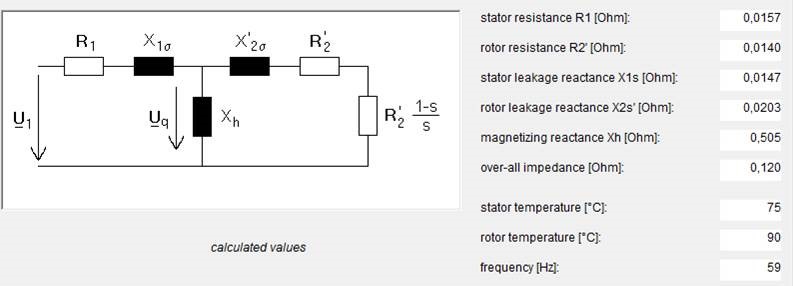
In my project, only the rotor resistance, inductance and leakage inductance are used,for the estimation of slip velocity.


The FAST estimation module and the SpinTAC module have been deleted and replaced.


This is the mechanical characteristic curve and the description of the motor used in the experiment.

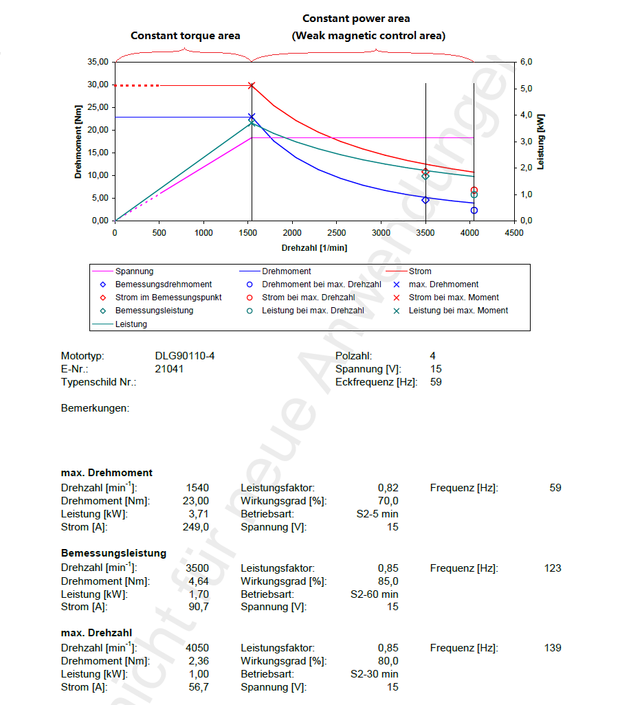
As shown in the figures, the motor in the constant torque region, the field current(Id) is a constant value, the torque current(Iq) is determined by the speed loop.


If we want to improve the speed of the motor, make the motor work in constant power area,

What we need to do is to reduce the field current(Id) of the motor.


Simple effective Field Weakening control strategy is as follows:

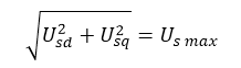
Iq has the following limits:

But I found some phenomena in recent debugging. When the motor is running at 3.5krpm, No matter how I change the value of Id_ref, the motor can not achieve the rated torque(0.67Nm), now the torque is only half of the rated.

Obviously, in 24V, the control is already saturated:

So I improved the bus voltage from 24 to 30V, at this time the motor torque can reach the rated value.


So, If the weak magnetic control is not the reason, what causes the motor torque to be unable to reach the rated value?

I hope that we can discuss this problem, to help me solve this problem.

  • This is the equivalent circuit of the motor and its parameters.

  • are you using a modulation value of 0.5?

    you may need to use a current sampling / reconstruction technique to allow you to increase the modulation to 0.67 which will use the full bus voltage of the system

    see proj_lab10a for details

    very impressed to see you make the necessary changes in MotorWare to customize your project!

  • Hi Chris,

    I tried the modulation control.

     I adjust USER_MAX_VS_MAG_PU to 1.3333, and  remove current sampling / reconstruction technique from lab10a to lab13e .

    The torque output of the motor is slightly larger than before.

    Another strange phenomenon has emerged, If the magnetizing current is increased, the motor will be out of control.

    So over modulation may not be the main reason? Or did I miss something about it ?

    //Add the following code in main()
    
    // Initialize and setup the 100% SVM generator
      svgencurrentHandle = SVGENCURRENT_init(&svgencurrent,sizeof(svgencurrent));
    
      {
        float_t minWidth_microseconds = 2.0;
        uint16_t minWidth_counts = (uint16_t)(minWidth_microseconds * USER_SYSTEM_FREQ_MHz / 2.0) + HAL_PWM_DBFED_CNT;
    
        SVGENCURRENT_setMinWidth(svgencurrentHandle, minWidth_counts);
      }
    
      //Add the following code in mainISR()


    // run the current reconstruction algorithm SVGENCURRENT_RunRegenCurrent(svgencurrentHandle, (MATH_vec3 *)(gAdcData.I.value)); // run the current ignore algorithm { uint16_t pwmValue_1 = HAL_readPwmCmpA(halHandle,PWM_Number_1); uint16_t pwmValue_2 = HAL_readPwmCmpA(halHandle,PWM_Number_2); uint16_t pwmValue_3 = HAL_readPwmCmpA(halHandle,PWM_Number_3); // run the current ignore algorithm SVGENCURRENT_RunIgnoreShunt(svgencurrentHandle,pwmValue_1,pwmValue_2,pwmValue_3); } // Set trigger point in the middle of the low side pulse HAL_setTrigger(halHandle,SVGENCURRENT_getMinWidth(svgencurrentHandle));


  • which version of MW are you using?

    the later versions of SVGENCURENT have a limit of 0.667, now 1.333

  • motorware_1_01_00_16,Today, I tried this version.

       "the later versions of SVGENCURENT have a limit of 0.667, now 1.333"

    Do you mean this:

    In the CTRL_setParams () function, there are the following code

    	// set the maximum modulation for the SVGEN module
    	maxModulation = SVGEN_4_OVER_3; //_IQ(MATH_TWO_OVER_THREE);
    	SVGEN_setMaxModulation(obj->svgenHandle,maxModulation);

    But I did not find any function to use the value of maxModulation. And  in my code , maxModulation has always been equal to SVGEN_4_OVER_3;

  • from proj_lab10a

      // set overmodulation to maximum value
      gMotorVars.OverModulation = _IQ(MATH_TWO_OVER_THREE);

                //Set the maximum current controller output for the Iq and Id current controllers to enable
                //over-modulation.
                //An input into the SVM above 1/SQRT(3) = 0.5774 is in the over-modulation region.  An input of 0.5774 is where
                //the crest of the sinewave touches the 100% duty cycle.  At an input of 2/3, the SVM generator
                //produces a trapezoidal waveform touching every corner of the hexagon
                CTRL_setMaxVsMag_pu(ctrlHandle,gMotorVars.OverModulation);

  • Dear Stefan Du,

    I saw in your project, the Encoder feedback is used. I also want to use ENC and QEP module of Motorware to get the speed information for sensorred controlling but I did not get the stable result. I think I don't want to know how to use the ENC module truly. So please share your experience about using ENC module in your project.

    For more my issue, please refer to the topic at: e2e.ti.com/.../501438

    Thank you in advance!
  • Hi,

    Frist , What type of motor is your motor?

    If it is a AC asynchronous motor :

    Motor rotor flux angle = Mechanical angle of motor rotor * Motor pole pairs + Motor slip angle .

    If it is a PMSM motor :

    Motor rotor flux angle = Mechanical angle of motor rotor * Motor pole pairs   .

    In the program, the angle is obtained by means of a velocity integral.

    I did the experiment with the AC motor, so I took it as an example:

    here is the code:

     //in user.h , Add Code:
    #define USER_ENC_SAMPLE_PERIOD           15000/USER_NUM_PWM_TICKS_PER_ISR_TICK/(USER_MOTOR_MAX_SPEED_KRPM*1000/60 *2)     
    
    //in main()
    	// initialize the ENC module
    	encHandle = ENC_init(&enc, sizeof(enc));
    
    	// setup the ENC module
    	HAL_Obj *hal_obj = (HAL_Obj *)halHandle;
    	ENC_setup(encHandle, hal_obj->qepHandle[0], USER_ENC_SAMPLE_PERIOD, \
    			USER_MOTOR_NUM_POLE_PAIRS, USER_MOTOR_ENCODER_LINES, \
    			0, USER_IQ_FULL_SCALE_FREQ_Hz, USER_ISR_FREQ_Hz, 8000.0);


    //in interrupt void mainISR(void)  , Modify code:
    
    	if(USER_MOTOR_TYPE == MOTOR_Type_Induction)
    	{
    		if(stCnt++ >= ISR_TICKS_PER_SPINTAC_TICK)
    		{
    			ElecSlip_calculate(ctrlHandle);    // Calculate Slip Velocity
    			ENC_setIncrementalSlip(encHandle, _IQmpy(_IQ(SlipVelocity), _IQ(gUserParams.ctrlPeriod_sec)));
    			stCnt = 1;
    		}
    		ENC_run(encHandle);                    // compute the electrical angle and motor speed
    		CTRL_run(ctrlHandle,halHandle,&gAdcData,&gPwmData,ENC_getMagneticAngle(encHandle));
    	}
    
    //in  updateGlobalVariables_motor()  , Modify code:
    
    	// get the speed From the ENC
    	gMotorVars.Speed_krpm =_IQ((float)ENC_getSpeedRPM(encHandle)*1.0/1000);
    
    //in enc.c   , Modify code:
    void ENC_run(ENC_Handle encHandle)
    {
    	uint16_t dir;
    	ENC_Obj *enc;
    	int32_t enc_val;
    	int32_t delta_enc;
    	int32_t temp;
    
    	// create an object pointer for manipulation
    	enc = (ENC_Obj *) encHandle;
    
    	// read the encoder
    	enc_val = QEP_read_posn_count(enc->qepHandle);
    
    	/*********************/
    	/* compute the ANGLE */
    	/*********************/
    	// compute the mechanical angle
    	temp = enc_val*enc->mech_angle_gain;
    	// add in calibrated offset
    	temp += enc->enc_zero_offset;
    	// convert to electrical angle
    	temp = temp * enc->num_pole_pairs;
    	// wrap around 1.0 (Q24)
    	temp &= ((uint32_t) 0x00ffffff);
    	// store encoder electrical angle
    	enc->enc_elec_angle = (_iq)temp;
    
    	// update the slip angle
    	enc->enc_slip_angle = enc->enc_slip_angle + enc->incremental_slip;
    	// wrap around 1.0 (Q24)
    	enc->enc_slip_angle &= ((uint32_t) 0x00ffffff);
    	// add in compensation for slip
    	temp = temp + enc->enc_slip_angle;
    	// wrap around 1.0 (Q24)
    	temp &= ((uint32_t) 0x00ffffff);
    	// store encoder magnetic angle
    	enc->enc_magnetic_angle = (_iq)temp ;
    
    	/*********************/
    	/* compute the SPEED */
    	/*********************/
    	enc->sample_count ++;
    	// if it reaches the sample period, read and process encoder data
    	if (enc->sample_count >= enc->sample_period)//
    	{
    		enc->sample_count = 0;
    		// read QEP direction from quadrature direction latch flag
    		dir = (QEP_QEPSTS_QDF&QEP_read_status(enc->qepHandle))>>5;
    		if(enc->prev_enc == -1)
    		{
    			enc->prev_enc = enc_val;
    		}
    		else
    		{
    			if(enc->prev_enc == enc_val)//mootor stop
    			{
    				delta_enc = 0 ;
    			}
    			else if(dir==1)//motor forward
    			{
    				if(enc_val > enc->prev_enc) //motor not pass reset point
    				{
    					delta_enc = enc_val - enc->prev_enc;
    				}
    				else//motor pass reset point
    				{
    					delta_enc = enc_val + (4*enc->num_enc_slots-1) - enc->prev_enc;
    				}
    			}
    			else if(dir == 0)//motor reversal
    			{
    				if(enc_val < enc->prev_enc) //motor not pass reset point
    				{
    					delta_enc = enc_val - enc->prev_enc;
    				}
    				else  //motor pass reset point
    				{
    					delta_enc = enc_val-(enc->prev_enc+ (4*enc->num_enc_slots-1) );
    				}
    			}
    			enc->prev_enc=enc_val;
    		}
    		enc->delta_enc = delta_enc;


    		temp = enc->delta_enc*enc->speed_gain;
    
    		enc->speed_lpf_out = temp;
    	}
    } // end of ENC_run() function
    
    int16_t ENC_getSpeedRPM(ENC_Handle encHandle)
    {
    	ENC_Obj *enc;
    	_iq temp;
    
      // create an object pointer for manipulation
      enc = (ENC_Obj *) encHandle;
    
      temp = (enc->speed_lpf_out >> ENC_RPM_Q1);
      temp = (temp * enc->rpm_gain) >> ENC_RPM_Q2;
    
      return (int16_t) temp;
    } // end of ENC_getSpeedRPM() function

    You can get the speed in the ENC_getSpeedRPM function.

    Please study the TI official code,  FOC theoretical knowledge and the relevant knowledge of AC motor,you can benefit a lot from it.

  • Today, I found an important step in the process.

    in constant power area:

    As we Know, Iq is limited by Imax and Id.

    Id is set by the weak magnetic control.

    However, Imax is not a constant value !!!

    Imax is affected by the performance of the motor itself, if the Imax setting is too high, when the torque increases, the motor voltage saturation, Iq settings will be too large for the Iq current loop, the motor will lose control.

    In the constant power area, the motor at different speeds, you assign the value of Id and Iq, limiting the value of Imax, so that the motor to play the best performance.

  • Hi Chris,

    In CTRL_Obj , I want delete I want to delete these structures , but after I delete, the program seems to be wrong .

    Can you Show me how to remove them correctly.

    In CTRL_Obj:

    EST_Handle         estHandle;

    TRAJ_Handle trajHandle_Id; 
    TRAJ_Obj traj_Id; 

    TRAJ_Handle trajHandle_spd; 
    TRAJ_Obj traj_spd; 

    TRAJ_Handle trajHandle_spdMax; 
    TRAJ_Obj traj_spdMax;

    In HAL_Obj:

    DRV8301_Handle drv8301Handle;
    DRV8301_Obj drv8301; 

  • Stefan,
    I'm confused. Why do you want to remove these object?

    The HAL_Obj you always need, no matter what.

    The DRV8301 can be removed if you aren't using a DRV8301 chip obviously....

    I suppose if you are doing sensored control you can remove EST_Handle.

    If you are skipping Motor ID you could do without the TRAJ handles, but they are part of the ROM.

    Are you using any of the ROM? Are you using the SpinTAC libraries for MOTION?


    Have you looked at proj_lab11x? These are a simplified version where we no longer have the FOC in CTRL but rather in-line in the code. This may be something you look at doing. There are -MOTION versions with ENC (but dual motor) in 12c and 13f.
  • Dear Stefan Du,

    Thanks a lot for your sharing. But I have some questions for your code:

    1. I studied the TI official code for ENC module (in Motorware 15) and found that, the ENC_setup() and ENC_run() functions don't look like as your functions that you share above. Namely, in TI's enc.h/enc.c module the prototype of these functions is:

    //! \brief Initializes encoder object parameters
    //! \param[in] encHandle                        Handle to the ENC object
    //! \param[in] sample_period                    How often the encoder is read & processed
    //! \param[in] num_pole_pairs                   Number of pole pairs in motor
    //! \param[in] num_enc_slots                    Number of encoder slots
    //! \param[in] enc_zero_offset                  Encoder zero offset in counts
    //! \param[in] full_scale_freq                  Full scale speed for normalization
    //! \param[in] speed_update_freq                Update frequency in Hz for speed calculation
    //! \param[in] speed_cutoff                     Speed calculation LPF cutoff frequency in Hz
    extern void ENC_setup(ENC_Handle encHandle, const int16_t sample_period,
                          const uint16_t num_pole_pairs, const uint16_t num_enc_slots, 
                          const uint32_t enc_zero_offset, const float_t full_scale_freq, 
                          const float_t speed_update_freq, const float_t speed_cutoff);
    
    //! \brief Based on the encoder reading, computes the electrical angle and the electrical "speed" (filtered speed)
    //! \param[in] encHandle				Handle to the ENC object
    //! \param[in] posnCounts               Current position counts from encoder
    //! \param[in] indextFlag               If set, there was an index
    //! \param[in] dirFlag                  Indicates direction of rotation
    //! \param[in] log_flag					If set, logs the encoder data
    //! \return								Nothing
    void ENC_run(ENC_Handle encHandle, uint32_t posnCounts, uint16_t indextFlag, uint16_t dirFlag, int16_t log_flag);

    So which Motorware version are you using? Or are these function which you modified from TI's functions?


    2. In your define:

    #define USER_ENC_SAMPLE_PERIOD           15000/USER_NUM_PWM_TICKS_PER_ISR_TICK/(USER_MOTOR_MAX_SPEED_KRPM*1000/60 *2)

    What does the number "15000" mean? Whether you mean to define for the motor with POLE_PAIRS = 2?

    3.  In my project, the motor type is an Induction Motor, and I understand that: 

    Motor rotor flux angle = Mechanical angle of motor rotor * Motor pole pairs + Motor slip angle .

    But how I get the "motor slip angle" with Motorware?

    I'm very grateful to your feedback!

  • 1. motorware_1_01_00_16, but ENC_setup() and ENC_run() functions are modified according to the function provided by TI. 

    Under careful study of these codes, you will be able to understand the logic of these functions.

    2. 15000 is the frequency of the main interrupt,  15000/USER_NUM_PWM_TICKS_PER_ISR_TICK = USER_ISR_FREQ_Hz ;

    #define USER_ENC_SAMPLE_PERIOD  USER_ISR_FREQ_Hz/(USER_MOTOR_MAX_SPEED_KRPM*1000/60 *2)

    In my algorithm to calculate the speed of the motor, the frequency of the sampling encoder is two times the maximum rotation frequency of the motor.
    This is why the definition should be *2.


    3. You can get the slip through the STPOSCONV_getSlipVelocity() function , check lab13e.


  • Thanks Chris,

    Yes, I'm doing sensored control .

    The EST module and the TRAJ module are embedded in the ROM in 28069, and in my project, I don't need them now.

    So maybe I could change a DSP chip with best cost performance, do you have any suggestions?
  • Dear Stefan Du,

    Thank you for your explanation. I have one more two suggestions for you:

    1. Whether you can share your code of the modified ENC_setup() function or not? Because I used the TI's ENC_setup() and ENC_run(), but I got the unstable result when trying to read the speed info by ENC_getSpeedRPM() and ENC_getFilteredSpeed(). Although I tested my hardware and encoder with ControlSUITE's functions and I got the good result.

    2. Because I am developing my project with F28054F which have not supported for SpinTAC function, so that whether I can get the slip through the STPOSCONV_getSlipVelocity() as you suggested or I must use an other module, for example SLIP.C/SLIP.H?

    Many thanks for your sharing!

  • Read some master's thesis or doctoral thesis on the calculation of motor slip , Finally, you will find this is a very simple algorithm. 
    A year ago I was like you, after you learn the depth of the FOC theory, you will find that FOC control and flux estimation are very simple.


    void ENC_setup(ENC_Handle encHandle, QEP_Handle qepHandle, \
    		const int16_t sample_period, const uint16_t num_pole_pairs,\
    		const uint16_t num_enc_slots, const uint32_t enc_zero_offset, \
    		const float_t full_scale_freq, const float_t speed_update_freq,\
    		const float_t speed_cutoff)
    {
      ENC_Obj *enc;
      float_t temp;
      float_t speed_cutoff_radians;
      int16_t i;
    
      // create an object pointer for manipulation
      enc = (ENC_Obj *) encHandle;
    
      // setup the encoder sample rate
      enc->sample_count = 0;
      enc->sample_period = sample_period;
    
      // copy the spi handle into the data structure
      enc->qepHandle = qepHandle;
    
      // copy the parameters into the data structure
      enc->num_enc_slots = num_enc_slots;
      enc->num_pole_pairs = num_pole_pairs;
      enc->enc_zero_offset = enc_zero_offset;
      enc->full_scale_freq = full_scale_freq;
      enc->delta_enc = 0;
      enc->prev_enc = -1;
    
      // initialize the electrical angle
      enc->enc_elec_angle = 0;
    
      // compute the gain which translates the mech into the elec angle
      enc->mech_angle_gain = (_iq)((((uint32_t)1)<<24)/(4*num_enc_slots));
    
      // compute the speed gain
      temp = ((float_t) speed_update_freq*ENC_SPEED_SCALING_FACTOR) / (4.0*(float_t)num_enc_slots*full_scale_freq*(float_t)sample_period);
      //temp = ((float_t) speed_update_freq*60) / (4.0*(float_t)num_enc_slots*(float_t)sample_period);
      enc->speed_gain = (int32_t) temp;
    
      // compute the rpm gain
      temp = (float_t)((full_scale_freq*60.0));
      enc->rpm_gain = (int32_t) temp;
    
      // compute the speed coefficients and initialize the low-pass filtered output
      enc->speed_cutoff = speed_cutoff;
      speed_cutoff_radians = ENC_2PI*speed_cutoff;
      temp = speed_cutoff_radians/(speed_update_freq+speed_cutoff_radians);
      enc->speed_lpf_cx = (int32_t) (ENC_SPEED_COEFF_SCALING*temp);
      enc->speed_lpf_cy = ENC_SPEED_COEFF_SCALING - enc->speed_lpf_cx;
      enc->speed_lpf_out = 0;
    
      // setup the encoder log
      enc->log_state        = ENC_LOG_STATE_IDLE;
      enc->run_flag         = 0;
      enc->trigger_idx      = 0;
      enc->trigger_delta    = 0;
      enc->log_idx          = 0;
      enc->post_trigger_len = ENC_LOG_LEN>>1;
      enc->post_trigger_cnt = enc->post_trigger_len;
      for (i=0; i<ENC_LOG_LEN; i++)
      {
      	enc->log[i] = 0;
      }
    
      // set up the QEP peripheral
    
      // hold the counter in reset
      QEP_reset_counter(qepHandle);
    
      // set the QPOSINIT register
      QEP_set_posn_init_count(qepHandle, 0);
    
      // disable all interrupts
      QEP_disable_all_interrupts(qepHandle);
    
      // clear the interrupt flags
      QEP_clear_all_interrupt_flags(qepHandle);
    
      // clear the position counter
      QEP_clear_posn_counter(qepHandle);
    
      // setup the max position
      QEP_set_max_posn_count(qepHandle, (4*num_enc_slots)-1);
    
      // setup the QDECCTL register
      QEP_set_QEP_source(qepHandle, QEP_Qsrc_Quad_Count_Mode);
      QEP_disable_sync_out(qepHandle);
      QEP_set_swap_quad_inputs(qepHandle, QEP_Swap_Not_Swapped);
      QEP_disable_gate_index(qepHandle);
      QEP_set_ext_clock_rate(qepHandle, QEP_Xcr_2x_Res);
      QEP_set_A_polarity(qepHandle, QEP_Qap_No_Effect);
      QEP_set_B_polarity(qepHandle, QEP_Qbp_No_Effect);
      QEP_set_index_polarity(qepHandle, QEP_Qip_No_Effect);
    
      // setup the QEPCTL register
      QEP_set_emu_control(qepHandle, QEPCTL_Freesoft_Unaffected_Halt);
      QEP_set_posn_count_reset_mode(qepHandle, QEPCTL_Pcrm_Max_Reset);
      QEP_set_strobe_event_init(qepHandle, QEPCTL_Sei_Nothing);
      QEP_set_index_event_init(qepHandle, QEPCTL_Iei_Nothing);
      QEP_set_index_event_latch(qepHandle, QEPCTL_Iel_Rising_Edge);
      QEP_set_soft_init(qepHandle, QEPCTL_Swi_Nothing);
      QEP_disable_unit_timer(qepHandle);
      QEP_disable_watchdog(qepHandle);
    
      // setup the QPOSCTL register
      QEP_disable_posn_compare(qepHandle);
    
      // setup the QCAPCTL register
      QEP_disable_capture(qepHandle);
    
      // renable the position counter
      QEP_enable_counter(qepHandle);
    
      return;
    } // end of ENC setup function

  • Dear Stefan Du,

    Thank you for your sharing the code, I want you confirm that:

    1. Did you modify the struct ENC_Obj as the following code?

    //! \brief Defines the encoder object
    //!
    typedef struct _ENC_Obj_
    {
      int16_t sample_count;			//!< when it reaches the sample period, collect & process encoder data
      int16_t sample_period;		//!< sample period of encoder processing
      uint16_t num_pole_pairs;		//!< number of pole pairs in motor
      uint16_t num_enc_slots;		//!< number of encoder slots
      _iq mech_angle_gain;			//!< gain which converts the encoder counts to Q24 mechanical degrees
      uint32_t enc_zero_offset;     //!< encoder zero offset in counts
      int32_t enc_elec_angle;		//!< encoder current electrical angle
      int32_t incremental_slip;     //!< incremental amount of slip
      int32_t enc_slip_angle;       //!< amount of total slip
      int32_t enc_magnetic_angle;   //!< encoder current magnetic angle (compensated for slip)
      int32_t prev_enc;				//!< previous encoder reading
      int32_t delta_enc;			//!< encoder count delta
      float_t full_scale_freq;	    //!< full scale frequency
      int32_t speed_gain;			//!< gain which converts a difference in encoder counts to Q24 normalized electrical freq
      int32_t rpm_gain;				//!< gain which converts the Q24 normalized electrical freq to RPM
      float_t speed_cutoff;		    //!< speed cutoff frequency in Hz
      int32_t speed_lpf_cx;			//!< speed input coefficient
      int32_t speed_lpf_cy;			//!< speed output coefficient
      int32_t speed_lpf_out;		//!< speed lpf output
      ENC_LOG_State_e log_state;	//!< encoder log state
      int16_t run_flag;				//!< encoder log free run flag
      int16_t post_trigger_len;		//!< encoder log post trigger length
      int16_t post_trigger_cnt;		//!< encoder log post trigger counter
      int16_t trigger_idx;			//!< index where trigger event happened
      int16_t trigger_delta;		//!< calculated delta when trigger happened
      int32_t log_idx;			    //!< encoder log index
      int16_t log[ENC_LOG_LEN];     //!< encoder log length
    #ifdef QEP
      QEP_Handle    qepHandle;   //!< the QEP handle
    #endif
    } ENC_Obj;

    2. The ElecSlip_calculate() function  in the code section below is yours, right? Because I could not see the content of it in TI's functions.

    	if(USER_MOTOR_TYPE == MOTOR_Type_Induction)
    	{
    		if(stCnt++ >= ISR_TICKS_PER_SPINTAC_TICK)
    		{
    			ElecSlip_calculate(ctrlHandle);    // Calculate Slip Velocity
    			ENC_setIncrementalSlip(encHandle, _IQmpy(_IQ(SlipVelocity), _IQ(gUserParams.ctrlPeriod_sec)));
    			stCnt = 1;
    		}
    		ENC_run(encHandle);                    // compute the electrical angle and motor speed
    		CTRL_run(ctrlHandle,halHandle,&gAdcData,&gPwmData,ENC_getMagneticAngle(encHandle));
    	}
    

    For your advance about reading thesis (master or/and doctor) about FOC Sensorless, thank you. In fact, I've ever read some thesis already. Moreover, I also designed the simulation models for FOC (with sensor and sensorless) in Plecs and/or Matlab/Simulink. I know that, to estimated the rotor speed we need to know some motor's parameters the more exact, the better to sensorless control. Even if I ran my designs in Hardware-In-the-Loop (HIL) using the dSPACE DS1104 tool.

    However I want to develop the code using Motorware to build an prototype of VFD product. But I have only known to Motorware for 4 months. I think I still don't understand to use Motorware's API functions completely because of the lack of guiding documents.

    So that I am highly appreciate any support of Motorware's experienced users.

    Have a good Sunday!