This thread has been locked.

If you have a related question, please click the "Ask a related question" button in the top right corner. The newly created question will be automatically linked to this question.

TMS320F2806x ADC Hardware Setup- Low Pass Filter Cutoff freqency.

Ref: " An Overview of Designing Analog Interface With TMS320F28xx/28xxx DSCs"

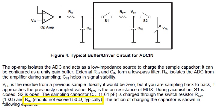
Q1: I want to measure DC Voltage. What should be cutoff frequency for low pass filter. as shown below.

Q2: Typical SNR is not provided in datasheet. How to calculate the ENOB for the same ADC.

Thanking you,

Siddharth Gupta

  • Hi Siddharth,

    You can make the cutoff as low as you want, but increasing the R and C will slow down the input charging of Csh. This will require a longer S+H window duration, which will slow down the sample-to-output latency and reduce the rate you can sample at. There is also a limit to how long you can make the S+h duration - check the ACQPS register setting in the TRM.

    If you are going to sample very infrequently, you can make the Cin >> (2^12) *Csh, so that all the charge for sampling comes from Cin. This will allow you to use a short S+H window duration. In this case you need to ensure that Cin has enough time to completely recharge before sampling again.

    Typical ENOB is around 10.3 bits, and this is limited by the SNR, so you can estimate the SNR as ~64dB.
  • Hi Devin, 

    Thanks for the reply.

    Vin = 3V DC

    Csh = 1.6 pF

    Cin >> (2^12)*Csh   

           >> 6.5 nF

    Assuming  Cin = 100nF, fc= 10Hz Cutoff LPF

    Rin = 1/(2*Pi*fc*Cin) = 159 Kohm

    Ref: "An Overview of Designing Analog Interface WithTMS320F28xx/28xxx DSCs"

    It mentions Rin should not be greater than 50 Ohm. (whereas I m getting around 159K).

    Kindly suggest where I am getting it wrong. And what should be the range of Rin.

    Thanking you,

    Siddharth Gupta

  • Hi Siddharth,

    If the external capacitance is very large, the S+H can be short even if Rin is very large, so that shouldn't be a problem. The criteria for this is the previously quoted Cin >> (2^12)*Csh. Otherwise, you need to ensure that the ADC S+H time is long enough that if the input voltage is full-scale, Csh can charge to within 1/4LSB of full-scale (starting fully discharged) in the allotted S+H time.

    For the large capacitor case, instead of the Csh charging time you need to account for the time required to charge the external capacitance. Whenever the ADC samples, the external voltage drops by around 1.6pF/100nF = 0.000016. If this is at full-scale, this is 3.3V*0.000016 = 53uV. If the allowed settling error is 1/4LSBs = 0.25*(3.3/4069) = 201uV, then we need to charge from (3.3V - 201uV - 53uV) to (3.3V - 201uV) between each sample. It requires -ln(254uV/3.3V) = 9.472 time constants to charge from 0 to the starting value and -ln(201uV/3.3V) = 9.706 time constants to charge from 0 to the final value, so it takes 9.706 - 9.472 = 0.234 time constants to go from start to end. This gives a time between samples of 0.234*100nF*159kOhms = 3.72ms, which is equivalent to about 268 samples-per-second. If you exceed this sample rate, the external circuit won't be able to keep up with the charge drawn into the ADC and the voltage will artificially drop over time. If you need to sample faster than this, and you need such a low filter cutoff frequency, then you will need to put the LP filter before an additional op-amp that drives the ADC with a low R and C value directly on the ADC pin.